Do you have a question about the Lincoln Electric RANGER 225 GXT and is the answer not in the manual?
| Brand | Lincoln Electric |
|---|---|
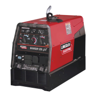
| Model | RANGER 225 GXT |
| Category | Welding System |
| Language | English |
Specific warnings regarding chemicals known to cause cancer, birth defects, or reproductive harm.
Guidelines for safe operation and maintenance of engine-powered equipment.
Information on potential hazards of electric and magnetic fields (EMF) during welding.
Critical warnings about the dangers of electric shock and preventative measures.
Precautions to protect against burns and eye damage from arc rays and sparks.
Information on avoiding health risks associated with welding fumes and gases.
Warnings and precautions to prevent fires and explosions caused by welding sparks.
Guidelines for the safe handling and storage of compressed gas cylinders.
Safety instructions for electrically powered equipment installation and use.
Strategies and techniques to minimize electromagnetic emissions from welding equipment.
Detailed technical data and specifications for the RANGER® 225 GXT.
General safety instructions and warnings related to equipment installation.
Procedures and requirements for properly grounding the welding machine.
Information on the requirement and installation of a spark arrestor.
Recommendations and considerations for safely towing the equipment.
Guidelines for securely mounting the equipment onto a vehicle.
Essential service checks and preparations before initial operation.
Instructions for filling fuel and checking oil levels before operation.
Procedure for correctly connecting and handling the equipment's battery.
Guidance on connecting and selecting appropriate welding output cables.
Information on the permissible operating angles for the engine.
Precautions and adjustments for operating the machine at high altitudes.
Recommendations for placing the welder to ensure proper airflow and ventilation.
Instructions for connecting various Lincoln Electric wire feeders to the welder.
Further safety guidelines for operating the welder with accessories.
Overview of the welder's output capabilities and operational parameters.
Details on the auxiliary power generation capabilities and output.
Guidance on selecting appropriate extension cords based on current and length.
Information on using auxiliary power simultaneously with welding.
Instructions for permanently installing the unit as a standby power source.
Essential safety warnings to be observed before operating the machine.
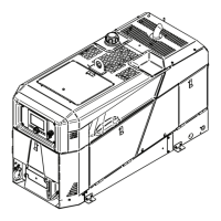
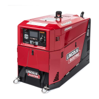
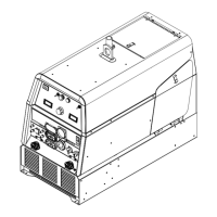
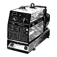
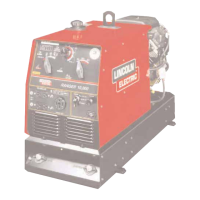
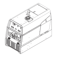
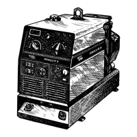
A brief overview of the RANGER® 225 GXT's design and purpose.
Explanation of the purpose and operation of the welder's controls.
How to use the Range switch to select amperage settings for different processes.
Function of the Control Dial for fine-tuning welding current and voltage.
Information on selecting and using the machine's polarity settings.
Estimated fuel consumption rates for various operating modes and loads.
Step-by-step procedures for starting and stopping the engine and machine.
Introduction to the different welding processes supported by the machine.
Procedures and settings for performing Stick (Constant Current) welding.
Guidance on using the machine for TIG (Constant Current) welding applications.
Instructions and settings for Wire Feed (Constant Voltage) welding.
Information on using the machine for limited arc gouging applications.
A concise summary table of welding process settings and operations.
Description of various optional field-installed accessories available for the welder.
List of recommended accessories for Stick, Wire Feed, TIG, and Plasma processes.
Recommended accessories for Stick welding applications.
Recommended guns and accessories for Wire Feed welding.
Recommended torches, modules, and accessories for TIG welding.
Recommended accessories for Plasma cutting applications.
General guidance on performing maintenance and service on the equipment.
Crucial safety warnings and precautions for performing maintenance tasks.
Daily checks and upkeep procedures to ensure proper machine function.
Detailed steps for draining and refilling the engine oil.
Specifications for the amount of oil required for engine refills.
Procedure for replacing the engine oil filter.
Maintenance tasks for the air cleaner and other general upkeep items.
Information regarding engine adjustments and potential overspeed hazards.
Inspection and maintenance guidelines for slip rings and brushes.
Safety and procedural information for handling and connecting the battery.
Notes on the types of fasteners used in the welder's construction.
Explanation of the fundamental components and their interaction in the system.
How rotor field feedback influences auxiliary power generation and control.
The role of the weld winding, reactor, and range switch in current control.
The function of the output bridge, choke, and polarity switch in delivering power.
Instructions on how to effectively use the troubleshooting guide to diagnose issues.
Specific steps for diagnosing and replacing printed circuit boards.
Troubleshooting steps for common issues related to welding and auxiliary power output.
Procedure for removing and replacing generator brushes.
Test to determine if correct DC voltage is applied to the rotor.
Test to identify shorted or grounded windings in the rotor.
Test to verify AC voltages generated by stator windings.
Test to determine if diodes in the output rectifier bridge are faulty.
Test to check the functionality of the flywheel alternator, regulator, and circuitry.
Test to verify correct engine RPM during high and low idle conditions.
Typical AC output voltage waveform under no-load conditions.
Typical DC output voltage waveform in Constant Voltage mode.
Typical DC output voltage waveform in Constant Current mode.
Typical AC output voltage waveform under load.
Example of an abnormal CV mode waveform indicating a fault.
Example of an abnormal DC mode waveform indicating a fault.
Correct CV mode waveform under open circuit conditions.
Correct DC mode waveform under open circuit conditions.
Correct AC output waveform under open circuit conditions.
Steps for removing and replacing the printed circuit board.
Inspection and maintenance for slip rings and brushes.
Procedure for removing and replacing the output rectifier bridge assembly.
Comprehensive procedure for removing and replacing the engine and/or rotor.
Specific steps for safely removing the rotor from the crankshaft.
Steps for reassembling the engine and rotor components after maintenance.
Procedures for retesting the machine after repairs or component replacement.
Complete wiring diagram for the RANGER® 225 GXT machine.
Overall schematic diagram of the RANGER® 225 GXT system.
Detailed schematic diagram for the control PC board.