EasyManua.ls Logo

Lincoln IDEALARC DC-400 User Manual

Lincoln IDEALARC DC-400
52 pages
To Next Page IconTo Next Page
Page #1 background imageLoading...
Page #1 background image
IMA 474A
June 1999
OPERATING MANUAL
IDEALARC
DC-400
(For Codes 1386 to 1462)
SAFETY DEPENDS ON YOU
Lincoln welders are designed and built with safety in mind. However, your overall safety can be increased
b
y proper installation .
.
.
and thoughtful oper
ation on y
our part. Read and observe the general safety
precautions on page 2 and f
ollo
w specific installation and oper
ating instr
uctions included in this manual.
Most importantly, think before you act and be careful.
THE LINCOLN ELECTRIC COMPANY
(AUSTRALIA) PTY. LTD.
A.B.N.
36 000 040 308
SYDNEY
.
A
USTRALIA
A Subsidiary of
THE LINCOLN ELECTRIC CO. U.S.A.
Associated Subsidiaries in Australasia, Asia, Canada, Europe, North and South America.
THE WORLD’S LEADER IN WELDING AND CUTTING PRODUCTS
ARC WELDING SUPPLIES - 07 847 7870

Table of Contents

Question and Answer IconNeed help?

Do you have a question about the Lincoln IDEALARC DC-400 and is the answer not in the manual?

Lincoln IDEALARC DC-400 Specifications

General IconGeneral
Input Voltage230/460 V
ProcessesStick, TIG
Input Frequency60 Hz
Duty Cycle60% @ 400A
Input Phase3

Summary

OPERATING MANUAL

SAFETY DEPENDS ON YOU

General safety advice for welder operation.

ARC WELDING SAFETY PRECAUTIONS

ELECTRIC SHOCK can kill

Precautions to prevent electric shock during arc welding.

FUMES AND GASES can be dangerous

Hazards of welding fumes and gases and ventilation advice.

ARC RAYS can burn

Protection against arc rays and suitable clothing recommendations.

WELDING SPARKS can cause fire or explosion

Precautions to prevent fires and explosions from welding sparks.

ARC WELDING SAFETY PRECAUTIONS (Continued)

CYLINDER may explode if damaged

Safety measures for handling compressed gas cylinders.

EQUIPMENT POWER SAFETY

Safety guidelines for electrically and engine-powered equipment.

WELDING, EMF & PACEMAKERS

Pacemaker Safety Precautions

Specific safety advice for welders with pacemakers.

Minimising EMF Exposure

Procedures to minimize exposure to electric and magnetic fields (EMF).

INSTRUCTIONS FOR ELECTROMAGNETIC COMPATIBILITY

EMC Conformance and Introduction

EMC standards, emissions, and interference.

Installation, Area Assessment, and Emission Reduction

Guidelines for installation, area assessment, and emission reduction methods.

MEANINGS OF GRAPHIC SYMBOLS

Power, Circuit Breaker, and Thermal Symbols

Symbols for power, breaker, and thermal protection.

Output, Arc, and Inductance Controls

Symbols for output, arc, and inductance adjustments.

MEANINGS OF GRAPHIC SYMBOLS (Continued)

Output Terminals, Voltmeter, and Arc Force Controls

Symbols for output terminals, voltmeter, and arc force.

Rating Plate Symbols

Symbols commonly found on the machine's rating plate.

MEANINGS OF GRAPHIC SYMBOLS (Continued)

Rating Plate Symbols (Continued)

Additional symbols from the rating plate.

MEANINGS OF GRAPHIC SYMBOLS (Continued)

Mode Switch and Connection Symbols

Symbols for mode switch and earth connection.

GENERAL MACHINE DESCRIPTION

Recommended Equipment and Design Summary

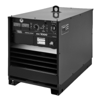
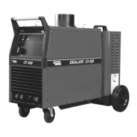
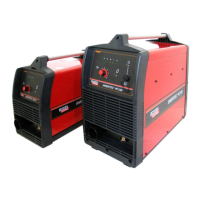
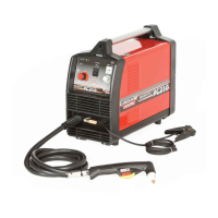
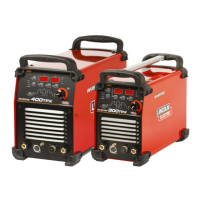
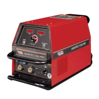
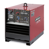
Compatible equipment and an overview of the welder's design.

Operational Features and Controls

Detailed description of the welder's controls and features.

GENERAL MACHINE DESCRIPTION (Continued)

Solid State Control Systems and Cooling

Explanation of control systems, cooling, and case features.

Welding Modes and Special Functions

Details on stick welding, arc controls, modes, and diode option.

Machine & Circuit Protection

Optional Equipment Overview

List of factory and field installed options.

Specific Options: Diode, Multi-Process, Capacitor Discharge

Details on diode, multi-process, and capacitor discharge circuits.

Machine & Circuit Protection (Continued)

Hi-Frequency Kit, Undercarriages, and Technical Specs

Information on Hi-Freq kit, undercarriages, and technical specifications.

INSTALLATION

Safety Precautions and Stacking Limits

General safety and stacking guidelines for installation.

Power and Cable Connections

Instructions for input power and output cable connections.

Correct Operational Use

Proper placement and usage of the machine.

INSTALLATION (Continued)

Output Cable Sizing and Field Option Installation

Cable size guidance and installation of field options.

Hi-Frequency Kit Installation and Components

Installation steps and components for Hi-Frequency kit.

INSTALLATION (Continued)

Multi-Process Switch and Wire Feeder Connections

Connecting multi-process switch and wire feeders.

DC-400 Connection Procedures

Specific connection steps for LN-22/LN-25 and multi-process switch.

OPERATING INSTRUCTIONS

Safety Precautions and Wire Feeder Notes

Safety warnings and notes for wire feeder operation.

Stick, TIG, Air/Carbon Arc Operation

Operating instructions for stick, TIG, and air/carbon arc processes.

POWER SOURCE OPERATION

Duty Cycle, Starting, and Output Controls

Duty cycles, machine start, and output control operations.

Polarity, Voltmeter, Thermal Light, and Mode Switches

Explanation of various switches and indicators.

POWER SOURCE OPERATION (Continued)

Arc Force, Arc Control, and Output Terminals

Details on arc force, arc control, and output terminals.

Auxiliary Power and Circuit Protection

Auxiliary connections and machine protection mechanisms.

MAINTENANCE

Routine Maintenance and Troubleshooting Introduction

Recommended maintenance and an introduction to troubleshooting.

TROUBLESHOOTING (continued)

Input Contactor and Output Issues

Troubleshooting problems with input contactor and lack of output.

Output Level and Control Issues

Troubleshooting low/high output and control problems.

TROUBLESHOOTING (continued)

Output, Shut-off, and Arc Quality Issues

Troubleshooting output, shut-off, and arc quality.

Control Functionality Troubleshooting

Diagnosing issues with output controls.

TROUBLESHOOTING (continued)

Arc Striking and Characteristics Troubleshooting

Troubleshooting poor arc striking and characteristics.

ARC CONTROL Functionality Troubleshooting

Diagnosing issues with the ARC CONTROL switch.

PROCEDURE FOR REPLACING PC BOARDS

Pre-Replacement Checks and Circuit Testing

Procedures for checking circuits before PC board replacement.

Control Rheostat and Switch Checks

Testing output controls, rheostats, and switches.

Power Rectifier Bridge Assembly Checking Procedure

Device Isolation and Diode Testing

Procedures for isolating components and testing diodes.

SCR Testing

Procedure for testing Silicon Controlled Rectifiers (SCRs).

GROUND TEST PROCEDURE

Test Preparation and Lead Removal

Steps for preparing the machine for ground testing.

Circuit Resistance Tests

Performing various resistance tests on machine circuits.

Parts List for DC-400

Parts List Overview

Introduction to the parts list section.

Illustration of Sub-Assemblies

Sub-Assembly Diagrams

Visual diagrams of the machine's sub-assemblies.

DC-400 For Codes: 1386 To 1462

Sub-Assembly Code Mapping

Table mapping codes to sub-assembly pages.

DC-400 For Codes: 1386 To 1462 (Continued)

Sub-Assembly Code Mapping (Continued)

Further mapping of codes to sub-assembly pages.

Optional Equipment Listing

Optional Equipment and Miscellaneous Items

Lists of optional equipment and miscellaneous parts.

Case Front Assembly

Case Front Assembly Diagram

Exploded view diagram of the case front assembly.

Case Front Assembly (Continued)

Case Front Assembly Parts List

Detailed parts list for the case front assembly.

Fan Baffle & Reconnect Panel

Fan Baffle & Reconnect Panel Diagram

Exploded view diagram of the fan baffle and reconnect panel.

Fan Baffle & Reconnect Panel (Continued)

Fan Baffle & Reconnect Panel Parts List

Detailed parts list for the fan baffle and reconnect panel.

Rectifier Bridge Assembly

Rectifier Bridge Assembly Diagram

Exploded view diagram of the rectifier bridge assembly.

Rectifier Bridge Assembly (Continued)

Rectifier Bridge Assembly Parts List

Detailed parts list for the rectifier bridge assembly.

Transformer & Lift Bale Assembly

Transformer & Lift Bale Assembly Diagram

Exploded view diagram of the transformer and lift bale assembly.

Transformer & Lift Bale Assembly (Continued)

Transformer & Lift Bale Assembly Parts List

Detailed parts list for the transformer and lift bale assembly.

Control Box Cover Assembly

Control Box Cover Assembly Diagram

Exploded view diagram of the control box cover assembly.

Control Box Cover Assembly (Continued)

Control Box Cover Assembly Parts List

Detailed parts list for the control box cover assembly.

Coil Assemblies

Coil Assemblies Diagram

Exploded view diagram of the coil assemblies.

Coil Assemblies (Continued)

Coil Assemblies Parts List

Detailed parts list for the coil assemblies.

Roof & Sides

Roof & Sides Diagram

Exploded view diagram of the roof and sides.

Diode Option

Diode Option Diagram

Exploded view diagram of the diode option assembly.

POWER RECTIFIER BRIDGE DIAGRAM 1

Power Rectifier Bridge Circuit Connections

Schematic showing connections of the power rectifier bridge.

WIRING DIAGRAM

Wiring Diagram and Primary Connection Table

Overall wiring diagram with primary connection references.

CAUTION & INPUT SUPPLY CONNECTION DIAGRAMS

High Voltage Warnings

Critical warnings regarding high voltage hazards.

Input Supply Connection Diagrams

Diagrams illustrating various input supply voltage connections.

Multi-Process Switch K804-1

Multi-Process Switch Information

Introduction to the Multi-Process Switch K804-1.

Multi-Process Switch (Continued)

Multi-Process Switch Diagram

Exploded view diagram of the Multi-Process Switch.

Multi-Process Switch (Continued)

Multi-Process Switch Parts List

Detailed parts list for the Multi-Process Switch.

LIMITED WARRANTY

Warranty Terms and Conditions

Overview of warranty periods, conditions, and limitations.

Warranty Repair and Customer Assistance

Procedures for warranty repair and customer assistance policies.

Related product manuals