
C
christinenortonSep 7, 2025
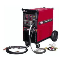
Why does wire bird nest while welding with Lincoln POWER MIG 300?
- HHunter MitchellSep 7, 2025
If wire bird nests while welding with your Lincoln Welding System, ensure the torch liner conduit is fully inserted so that it touches the inner black plastic wire guide. If the inner black plastic wire guide is worn out, replace it. Check that the Push-Pull torch drive rolls aren't set too tight, referring to the owner's manual for the proper setting. If the problem continues, lower your Stall Factor Number.