EasyManua.ls Logo

Lincoln CV-655 User Manual

Lincoln CV-655
109 pages
To Next Page IconTo Next Page
Page #1 background imageLoading...
Page #1 background image
SVM147-A
September, 2002
Return to Master TOC Return to Master TOC Return to Master TOC Return to Master TOC
View Safety Info View Safety Info View Safety Info View Safety Info
RETURN TO MAIN INDEX
Safety Depends on You
Lincoln arc welding and cutting
equipment is designed and built
with safety in mind. However,
your overall safety can be
increased by proper installation
. . . and thoughtful operation on
your part. DO NOT INSTALL,
OPERATE OR REPAIR THIS
EQUIPMENT WITHOUT READ-
ING THIS MANUAL AND THE
SAFETY PRECAUTIONS CON-
TAINED THROUGHOUT. And,
most importantly, think before
you act and be careful.
SERVICE MANUAL
For use with machine code number 10120 thru 10129
CV-655
• Sales and Service through Subsidiaries and Distributors Worldwide •
Cleveland, Ohio 44117-1199 U.S.A. TEL: 216.481.8100 FAX: 216.486.1751 WEB SITE: www.lincolnelectric.com
• World's Leader in Welding and Cutting Products •
Copyright © 2002 Lincoln Global Inc.

Table of Contents

Question and Answer IconNeed help?

Do you have a question about the Lincoln CV-655 and is the answer not in the manual?

Lincoln CV-655 Specifications

General IconGeneral
BrandLincoln
ModelCV-655
CategoryWelding System
LanguageEnglish

Summary

Safety Precautions

California Proposition 65 Warnings

Warnings regarding cancer and reproductive harm from diesel engine exhaust.

Electrical Shock Hazards

Critical safety instructions to prevent severe electrical shock.

Arc Rays, Fumes, and Sparks Safety

Guidelines for protection against arc rays, fumes, gases, and sparks.

Cylinder and Electrical Equipment Safety

Safety for compressed gas cylinders and electrical equipment.

Installation Guide

Technical Specifications and Symbols

Detailed technical data and explanation of rating plate symbols.

Installation Safety and Location

Essential safety warnings and guidance on choosing a suitable location.

Electrical Input and Output Connections

Steps for connecting power, fuses, wires, and output cables.

Auxiliary Power and Control Connections

Connecting auxiliary equipment and control devices via receptacles and terminals.

Operation Guide

Operating Safety Precautions

Critical safety guidelines to follow during machine operation.

Machine Description and Controls

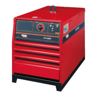
Overview of the CV-655, its features, capabilities, and operator controls.

Case Connections and Protection

Description of connections on the rear panel and protection systems.

Accessories

Wire Feeder Compatibility and Connection

List of compatible wire feeders and procedures for connection.

Field Installed Options

Available optional kits that can be installed by the user.

Maintenance

Maintenance Safety Precautions

Essential safety measures before performing any maintenance.

General Maintenance and Component Locations

Routine tasks and identification of major internal components.

Theory of Operation

Machine Operation Principles

Overview of the machine's operation, power input, and key circuits.

Protective Systems and SCR Function

Explanation of protective systems and SCR operation.

Troubleshooting and Repair Guide

Using the Troubleshooting Guide

Instructions on how to effectively use the guide to diagnose problems.

PC Board Troubleshooting Procedures

Steps for troubleshooting and replacing PC boards, including static precautions.

Common Problem Categories

Troubleshooting steps for output, function, and welding problems.

Key Component Test Procedures

Specific tests for trigger circuit, firing board, and transformers.

Diagnostic Aids: LEDs and Waveforms

Interpreting LED indicators and analyzing waveforms for diagnostics.

Component Replacement Procedures

Steps for replacing common components like contactors, SCRs, and transformers.

Retest After Repair Requirements

Requirements for retesting the machine after repairs or component replacement.

Electrical Diagrams

Wiring Diagrams

Wiring diagrams specific to different machine codes.

PC Board Schematics and Assemblies

Schematics and layouts for control, fan/snubber, and firing PC boards.

SVM Error Reporting

Related product manuals