LINCOS
®
AUTOMOTIVE TOOLS
20
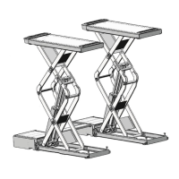
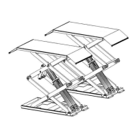
SCISSOR VEHICLE LIFT STD-5335A
6.1. CONTROL
EMERGENCY
STOP
INDICATOR
LIGHT
POWER
SWITCH
Controls for operating the lift are:
POWER SWITCH
The switch can be set in two positions:
• OFF position: the lift electric circuit is not
powered; the switch can be padlocked to
prevent the use of the lift.
• ON position: lift electric circuit is powered
INDICATOR LIGHT
It shows that the electric circuit is powered
UP BUTTON
When pressed, the motor and hydraulic circuit are
operated and the lift will be raised
DOWN BUTTON
When pressed, the lift will take seconds to release
the safety by means of the electromagnets and
then the lowering solenoid valve is powered: the
lift begins to lower under its weight and the load
lifted.
UP
LOCK
DOWN
6.2. TO RAISE THE LIFT
• Place the vehicle at the center of the
platform ;
• Place pads under the positions indicated for
lifting, by the motor vehicle’s manufacturer;
• Place rubber pads on the platforms where
the lifting points will contact and press UP
switch to lift the vehicle to 200mm~300mm
(9 to 12 inches) from the oor;
• Make sure that the two platforms are
leveled and nothing unusual is found;
• Keep pressing UP switch until the vehicle
rises to the required height, then press
LOCK switch..
• Press the SCRAM switch,the INDICATOR
LIGHT will be off.
6.3. TO LOWER THE LIFT
• Turn on the SCRAM switch;
• Press the DOWN switch;
• The lift will descend, under its own weight
and car’s one, to the safety height of
500mm;
• Drive away the vehicle until the lift is
lowered to ground completely