12
Installations remote from vertical wall
Fire dampers installed within vertical wall Fire dampers installed within oor Paired installation
Installation a [mm] b [mm] c [mm] d [mm]
Rigid wall
Installation remote from the vertical rigid wall
Mortar or plaster putty sealing
200 110 * - - No
Installation remote from the vertical rigid wall with Fire Batt
(Weichschott) sealing
Rock wool 140 kg/m³ and endothermic varnish sealing
200 110 * - - No
Flexible wall
Installation remote from the vertical light wall (plasterboard)
Plasterboard and rock wool 100 kg/m³ or mortar or plaster putty
sealing
200 110 * - - No
Installation remote from the vertical light wall (plasterboard)
with Fire Batt (Weichschott) sealing
Rock wool 140 kg/m³ and endothermic varnish sealing
200 110 * - - No
Installation remote from the vertical light wall (gypsum blocks
wall)
Mortar or plaster putty sealing
200 110 * - - No
Installation remote from the vertical light wall (gypsum blocks
wall) with Fire Batt (Weichschott) sealing
Rock wool 140 kg/m³ and endothermic varnish sealing
200 110 * - - No
Floor
EI 120 S Installation remote from the oor
Mortar or plaster putty sealing
- - 200 110 * No
EI 90 S Installation remote from the oor
Mortar or plaster putty sealing
- - 200 110 * No
* Due to rock wool panels thickness. See installation details.
Installations within vertical light wall (Shaft wall)
Fire dampers installed within vertical wall Fire dampers installed within oor Paired installation
Installation a [mm] b [mm] c [mm] d [mm]
Flex-
ible
wall
EI 60 S Installation within vertical light wall (Shaft wall)
Plasterboard and mortar or plaster putty sealing
200 75 - - No
Construction supports characteristics
The European standard for re dampers foresees a precise correlation
between the wall/oor characteristics and the re resistance class
obtained, as well as the correlation between wall/oor used for the
test and wall/oor used for the actual installation.
The test results obtained on a type of wall/oor are valid also for
walls/oor of the same type but with greater thickness and/or densi-
ty than those used in the test.
For plasterboard walls, the test results are also valid for walls with a
greater number of plasterboard layers on each side.
As a result, the indicated thickness and density characteristics are to
be considered as minimum values.
The wall/oor in which the re dampers are installed must be re
class certied according to the standards foreseen for the structure.
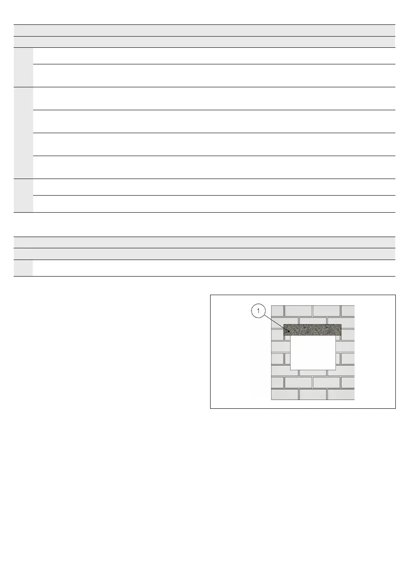
Rigid walls
Can be made with aerated concrete blocks, poured concrete, con-
crete panels, perforated cell elements in concrete or brick in accord-
ance with the following characteristics:
• minimum thickness 100 mm;
• minimum density 550 kg/m³.
The use of a reinforcing beam above the opening is recommended
for walls made from concrete blocks, bricks or in concrete cell ele-
ments.
For walls built with perforated elements, it is also recommended that
the area of the opening be made from full elements (for example
aerated concrete blocks) to guarantee the correct adhesion of the
mortar.
1. Reinforcing beam
Light plasterboard vertical walls
During testing, light plasterboard walls have been used with the fol-
lowing characteristics:
• U-shaped horizontal metal frame (50 mm) and C-shaped vertical
frame (49 mm) made from 0,6 mm thick sheet metal;
• Vertical proles placed with a maximum spacing of 625 mm be-
tween each other;
• Rock wool lling which has density 100 kg/m³;
• Each side is made from two plasterboard layers 12,5 mm thick, un-
alinged to avoid alignment between the joints of the layer above
and below.
The following indications are given for the installation walls:
• metal proles minimum width: 49 mm;
• metal proles minimum thickness: 0,6 mm;
• vertical proles placed with a maximum spacing of 625 mm be-
tween each other;
 Loading...