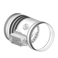
16
D1 Hole base: see table above
D2 Hole height: see table above
E Damper protrusion from the wall: see table above
S Wall minimum thickness: see table above
1. Plasterboard inll panel, thickness 12,5 mm
2. Self-drilling screw Ø 3,5 X 45 mm
Installations within oor
Refer to the section Construction supports characteristics for further
information.
Comply with the minimum distances indicated on section Minimum
distances .
Floor opening
A opening must be provided in the oor as indicated in the table
and in the drawing
Damper positioning
Position the damper in the opening so that the side of the closing
mechanism extends as indicated in the table and in the drawing.
Filling
Fill the space between the oor and the damper as indicated in the
table and in the drawing.
Fire resistance classication
Hole size “D1 x D2”
[mm]
Damper protrusion from the
oor “E”
[mm]
Floor minimum thickness “S”
[mm]
Sealing
EI 90 S Installation within oor
Floor minimum density 650 kg/m³
EI 90 S
(500 Pa)
From (B+70) x (H+70)
to (B+90) x (H+90)
185 100 Mortar sealing
EI 120 S Installation within oor
Floor minimum density 650 kg/m³
EI 120 S
(500 Pa)
From (B+70) x (H+70)
to (B+90) x (H+90)
170 150 Mortar sealing
EI 180 S Installation within oor
Floor minimum density 2200 kg/m³
EI 180 S
(500 Pa)
From (B+70) x (H+70)
to (B+90) x (H+90)
170 150 Mortar sealing
B Nominal base of the damper
H Nominal height of the damper
D1 Hole base: see table above
D2 Hole height: see table above
E Damper protrusion from the oor: see table above
S Floor minimum thickness: see table above
1. Mortar M-10, EN998-2
Installations within vertical wall with Fire Batt (Weichschott) sealing
Refer to the section Construction supports characteristics for further
information.
Comply with the minimum distances indicated on section Minimum
distances .
Wall opening
A opening must be provided in the wall as indicated in the table and
in the drawing
In case of paired installation refer to the section Fire dampers pairing
for further information
Damper positioning
Position the damper in the opening so that the side of the closing
mechanism extends as indicated in the table and in the drawing.
The re damper has to be xed at the bottom and suspended from
the ceiling.
 Loading...