INSTALLATION
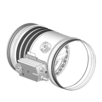
WH25
LINDAB SAFE
19/50
Installations within vertical rigid wall
Refer to the section Construction supports characteris-
tics p.17 for further information.
Comply with the minimum distances indicated on section
Minimum distances p.15.
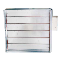
Wall opening
A opening must be provided in the wall as indicated in the
table and in the drawing
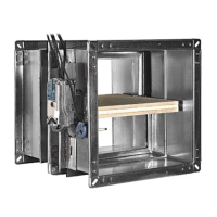
Damper positioning
Position the damper in the opening so that the side of the
closing mechanism extends as indicated in the drawing.
Filling
Fill the space between the wall and the damper as indicat-
ed in the table and in the drawing.
Fire resistance classi-
cation
“D” hole size
[mm]
Wall minimum thickness
“S”
[mm]
Sealing
EI 120 S Installation within vertical rigid wall
Wall minimum density 550 kg/m³
EI 120 S
(500 Pa)
From Ø + 25
to Ø + 440
(circular hole)
100 Mortar or plaster putty sealing
EI 90 S Installation within vertical rigid wall
Wall minimum density 550 kg/m³
EI 90 S
(500 Pa)
From (Ø + 50) x (Ø + 50)
To (Ø + 70) x (Ø + 70)
(square hole)
100
Rock wool 100 kg/m³ with
inll plasterboard (thickness
12.5 mm)
WH25
19/50
LINDAB SAFE