INSTALLATION
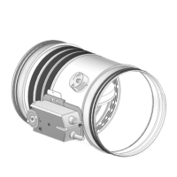
WH25
LINDAB SAFE
34/50
Installation within vertical light wall (Shaft wall)
Refer to the section Construction supports characteris-
tics p.17 for further information.
Comply with the minimum distances indicated on section
Minimum distances p.15.
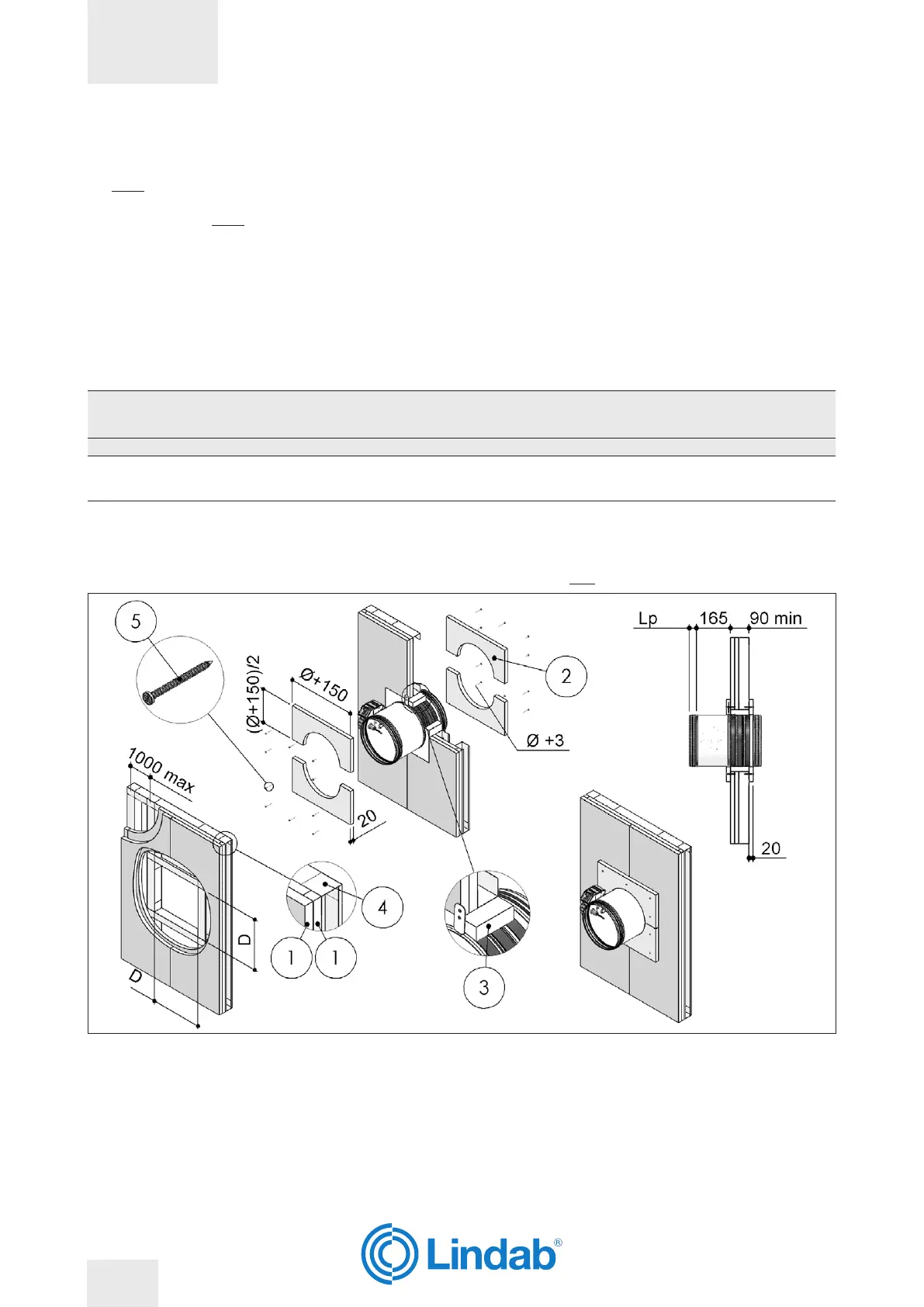
Wall opening
A opening must be provided in the wall as indicated in the
table and in the drawing
Damper positioning
Position the damper in the opening so that the side of the
closing mechanism extends as indicated in the table and
in the drawing.
Filling
Fill the space between the wall and the damper as indicat-
ed in the table and in the drawing.
Cover the sealing by applying on both faces of the wall a
layer of plasterboard, to a total minimum thickness of 20
mm per side, to make a frame with a side 150 mm greater
than the nominal diameter of the damper.
Fire resistance classi-
cation
“D” hole size
[mm]
Wall minimum thickness
“S”
[mm]
Sealing
EI 90 S Installation within vertical light wall (Shaft wall)
EI 90 S
(300 Pa)
From (Ø + 50) x (Ø + 50)
To (Ø + 70) x (Ø + 70)
(square hole)
90
Mortar or plaster putty with
inll plasterboard (thickness
20 mm)
1. Plasterboard thickness 20 mm
2. Plasterboard arch inll, thickness 20 mm
3. Mortar M-10, EN998-2 or plaster putty
4. Metal frame
5. Self-drilling screw Ø 3,5 X 45 mm
D Hole size: see table above
Lp Overlap length between re damper and duct: see section
Dimension p.11
WH25
LINDAB SAFE
34/50