03/27/08 Page 2 of 7
LINE 6 CONFIDENTIAL
1.
DO NOT WATER WASH THE BOARD: The potentiometers and tact switches are sensitive to water
washing. If wave soldering is preferred, we recommend using a no-clean flux wave soldering process, rather
than a process that requires washing. The fluxing process wave must be controlled so as not to have flux
migrate inside the switch through the top of the housing. Good venting is required. No-clean flux vapors can
enter the switch if adequate venting is not available. The vapors will condense on the internal contacts and
become an insulator when they solidify.
2. BREAKAWAY PCB: DO NOT BREAK APART THE FIVE SECTIONS OF THE PCB UNTIL
AFTER WAVE SOLDER.
3. DO NOT INSTALL PARTS: C10-11
4. POTENTIOMETERS: All potentiometers are to be mounted on the TOP SIDE of the User Interface
Lower PCB (35-00-0272-2). Potentiometers are to be flush to the PCB, and as straight as possible (Within +/-
1 degree). See Photo.
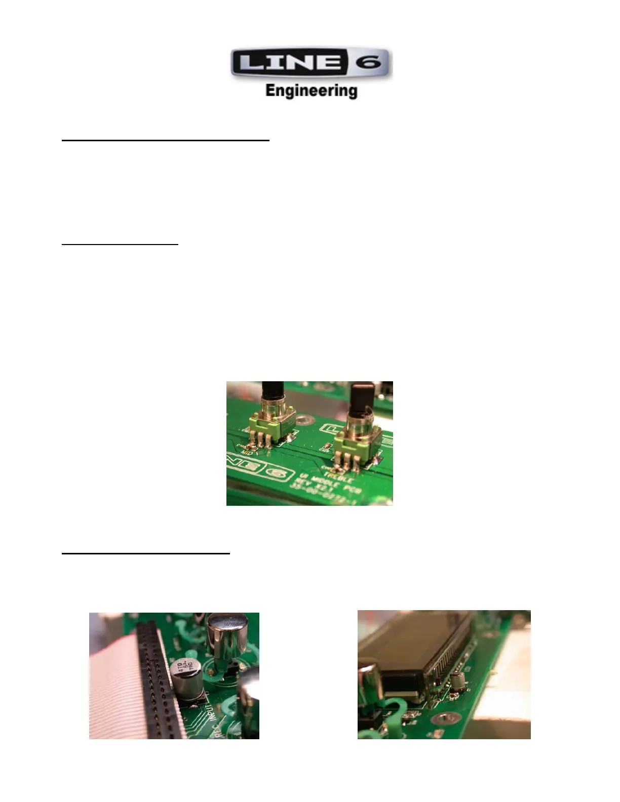
5. RADIAL LEAD CAPACITORS: RADIAL LEAD SM CAPACITORS: Check orientation of
electrolytic capacitors C3 and C7 located on the UI Upper PCB (35-00-0272). Radial lead capacitors are
mounted flush with the PCB and lined up with the silkscreen outline within +/-1 degree of accuracy.
See Photos.
 Loading...