Black 0009
Black0009
Solid State Outputs
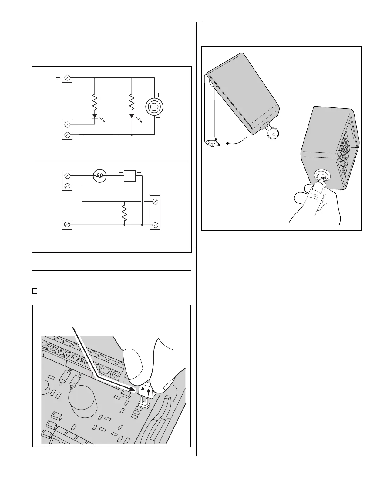
The two solid state outputs (Output #3 & Output #4) can
be programmed to activate during various conditions.
These outputs can be used to activate indicators or
sounders. See Figure 7 for wiring examples using the solid
state outputs.
Beeper Sound Level
The keypad’s beeper can be set to low or high level.
If the keypad’s beeper is too loud for the keypad’s
location, remove jumper JP1 (see Figure 8).
Locking Keypad
After the installation is complete. Lock the keypad using
the keylock (see Figure 9).
REMOVE JUMPER JP1 TO REDUCE
THE SOUND LEVEL OF THE BEEPER
Figure 8. Removing Beeper Jumper
HOOK KEYPAD
ONTO BACKPLATE
USE KEY TO
LOCK KEYPAD
Figure 9. Locking the Keypad Case
OUTPUT #3
OUTPUT #4
COMMON
GROUND
ACCESSKEY
POWER
1K
Ω
LED
1K
Ω
LED
ELECTRONIC
BEEPER
EXAMPLE 1: OUTPUT #3 LIGHTS AN LED,
OUTPUT #4 LIGHTS AN LED AND SOUNDS A BEEPER
EXAMPLE 2: OUTPUT #3 LIGHTS A LAMP POWERED FROM AN EXTERNAL
SOURCE, OUTPUT #4 TRIGGERS A NORMALLY OPEN ALARM PANEL ZONE
OUTPUT #3
OUTPUT #4
EACH
OUTPUT
100 mA
MAXIMUM
ALARM PANEL
N.O. ZONE
COMMON
END-OF-LINE
RESISTOR
POWER
SOURCE
LOW VOLTAGE
LAMP
EACH
OUTPUT
100 mA
MAXIMUM
Figure 7. Using the Solid State Outputs
9