HSLG Slide Gate Operator Installation Guide - 4 - P1220 Revision X8 6-22-2011
Gate Bracket and Chain Assembly
✓ NOTE: The item numbers shown in these illustrations
are for reference only. For the actual part numbers, refer
to the parts lists in the rear of this manual.
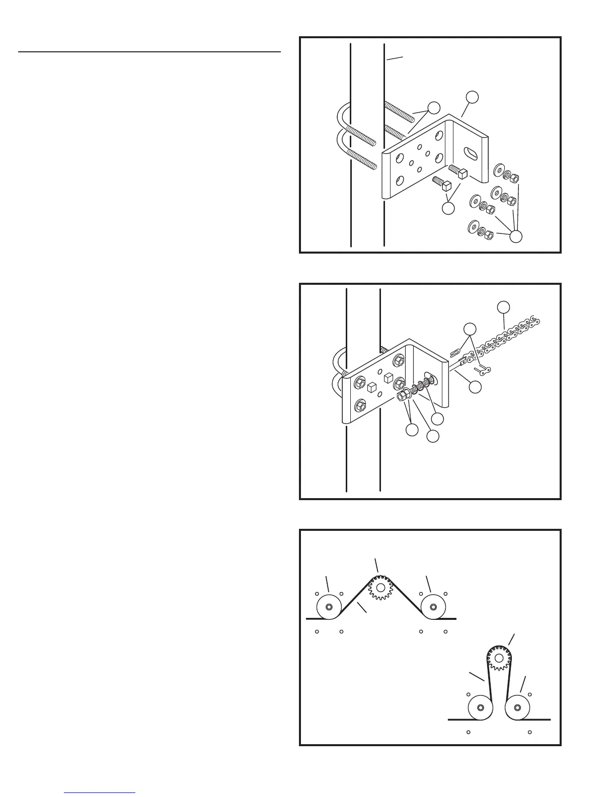
Assemble a gate bracket (1) to the front edge of the gate,
using two U-bolts (2), and mounting hardware (3). Before
tightening down completely, be sure the bracket is parallel
to the gate. Tighten the U-bolt hardware the rest of the way,
then screw the square head bolts (4) into the threaded
holes in the gate plate until they bottom out against the gate.
These will help keep the bracket from twisting on the pipe.
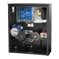
Slide a threaded chain pin (5) through the bracket as shown,
with spring (6), fl at washer (10), and two hex nuts (7). Attach
one end of the drive chain (8) to the chain pin using master
link (9) and begin unrolling the chain toward the operator.
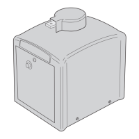
Remove the rain cover from the back of the slide gate
operator. Carefully thread the drive chain under the fi rst
idler, over the drive sprocket, and then under the last idler.
Make sure you feed most of the chain through the idlers and
sprocket before attaching the chain to the back end of the
gate.
Assemble the other gate bracket on the rear edge of the
gate, using the same process as the front gate bracket.
Once this is done, take the other chain pin, spring and jam
nuts and assemble with the end of drive chain and the other
master link.
At this point you should be able to adjust the chain tension
by tightening the jam nuts on each end. Approximately
1/4” to 3/8” of slack per foot of drive chain is acceptable.
Make sure the chain does not drag on the ground, across
the gate rollers or the idler frame of the operator.
Additional mounting holes have been provided in the gate
bracket for installer convenience.
END OF GATE PIPE SHOWN
REFERENCE ONLY
1
2
3
4
Figure 3. Mounting Gate Bracket to Gate
Figure 4. Chain Pin and Chain Assembly
8
9
5
6
7
10
NOTE: IDLER CONFIGURATION
MAY APPEAR DIFFERENT DEPENDING
ON THE SLIDE OPERATOR MODEL
DRIVE
SPROCKET
DRIVE SPROCKET
IDLER
WHEEL
IDLER WHEEL
CHAIN
PATH
CHAIN
PATH
IDLER WHEEL
Figure 5. Chain Path