HSLG Slide Gate Operator Installation Guide - 6 - P1220 Revision X8 6-22-2011
Operator Setup (Cont.)
Open and Close Limit Adjustment
The limit nuts are not preset at the factory and must be adjusted
for the gate in each installation. The limit switches are activated
by two threaded nylon rotary limit nuts which are attached to
a threaded limit shaft driven by a chain and sprockets from
the main drive shaft. REMOVE THE CARDBOARD FILLER
BEFORE ADJUSTING THE LIMIT NUTS.
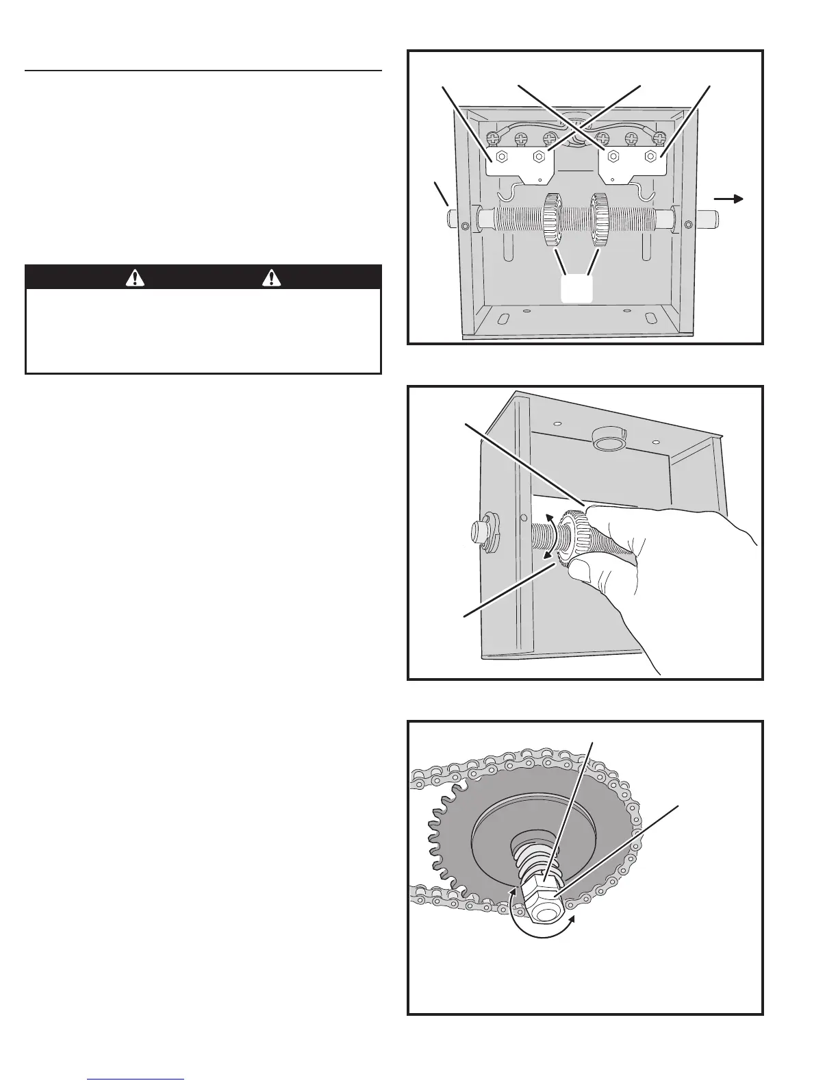
The Controller is factory setup for right hand installations.
The OPEN limit switch is the one closer to the front of the
operator. In left hand installations, the CLOSE limit switch is
the one closer to the front of the operator (see Figure 9).
Limit Nuts Rough Adjustment
Before running the operator, set the limit nuts as follows:
1. With the gate connected to the gate operator in a mid-travel position,
the power disconnect switch turned OFF, disconnect the operator
by using the manual disconnect lever, once the operator has been
disconnected, manually move the gate by hand to within a foot of
its fully open position (the foot of distance is necessary to allow for
coasting of the operator after the limit switch is tripped).
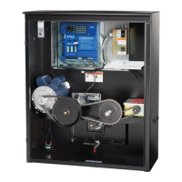
2. Once the gate is in this position, adjust the OPEN limit nut until it
activates the limit switch for open. Press down the detent plate and
rotate the nut along the threaded shaft (see Figure 10).
3. After setting the open limit, move the gate to one foot from fully
closed and repeat the process for the CLOSE limit nut.
Limit Nuts Fine Adjustment
After fi nishing the rough limit nut adjustments, reposition the
gate to approximately the center of travel.
1. Re-engage the operator using the disconnect handle.
2. Turn the power disconnect switch ON.
3. Stand clear of any moving parts and press the OPEN button.
4. After the gate opens, press the CLOSE button.
5. Observe the gate in both directions as it runs through each complete
cycle. Adjust the open or close limit nuts again if necessary. Fine levels
of adjustment can be made by adjusting a few teeth on the nut at a
time. If the gate stops during travel, you may need to adjust the Open or
Close Current Setting or the Maximum Run Timer (see Pages 12-13).
Torque Limiter Adjustments
Before adjusting the torque limiter, make sure the gate is in
good working condition. One person should be able to move
the gate by hand. Be certain the gate moves freely and
without binding throughout its travel. Torque limiters are set
light at the factory and must be adjusted during installation.
Adjust the torque limiter tight enough to keep it from slipping
during normal operation. See Figure 11.
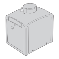
To adjust the torque limiter in model HSLG:
1. Loosen the jam nut.
2. To increase the output, turn the adjustment nut clockwise
one fl at, or 1/6 turn, at a time until desired output is obtained.
To reduce the output, turn the adjustment nut counterclockwise one
fl at, or 1/6 turn, at a time until desired output is obtained.
3. Tighten the jam nut against the adjustment nut when fi nished.
PRESS DETENT
PLATE DOWN
ROTATE
LIMIT NUT
Figure 10. Setting the Limits
Figure 11. Torque Limiter Adjustment
CAUTION
If the operator is installed in a left-hand installation. Set the
Controller to left-hand operation BEFORE running the operator
for the fi ne setting of the limit nuts. Failure to do so will result
in over-shooting the limit switches, and can cause damage to
the operator and/or gate. Refer to programming on Page 11.
LEFT-HAND INSTALLATION
OPEN LIMITCLOSE LIMIT
RIGHT-HAND INSTALLATION
OPEN LIMIT CLOSE LIMIT
LIMIT
NUTS
LIMIT
SHAFT
LIMIT
SWITCHES
FRONT OF
OPERATOR
Figure 9. Limit Box Assembly
ADJUSTMENT NUT
JAM NUT
TO INCREASE TORQUE
TURN ADJUSTMENT NUT
CLOCKWISE ONE FLAT
THEN RE-TEST
TO DECREASE TORQUE
TURN ADJUSTMENT NUT
COUNTERCLOCKWISE
ONE FLAT THEN RE-TEST
MORE
LESS
TIGHTEN JAM NUT
DURING TESTING
AND WHEN FINISHED !!!