HSLG Slide Gate Operator Installation Guide - 5 - P1220 Revision X8 6-22-2011
Operator Setup
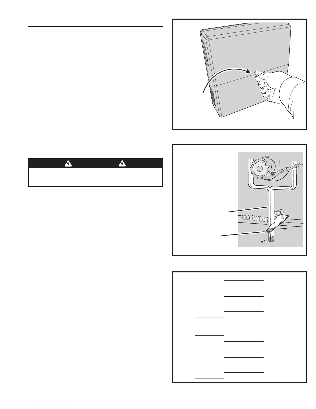
Controller Access
The Controller is protected by a plastic dust cover (single
phase models only). To remove the dust cover, loosen the
cover’s wing-screw and lift the cover off (see Figure 6).
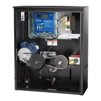
Manual Disconnect
The manual disconnect shifter lever and the locking lever
is illustrated in Figure 7. They can be found at the center
bottom of the operator cabinet. (The handle of each has
been fi nished in easy to spot red fi rm-grip coating.)
To disconnect the unit for manual operation, grasp the
handle of the spring-loaded shifter lever and pull it directly
toward you until the spring-loaded locking lever snaps into
place behind it. This action disengages the pinned shifter
block from the drive mechanism and holds the block in the
disengaged position.
To re-engage the operator, move the locking lever to the
right, releasing the spring-loaded shifter lever to snap back
into the engaged position.
AC Power Connection
All Linear gate operators are supplied with a power
disconnect switch to turn on and off the power available
to the operator. Following wiring specifi cations on Page 2,
incoming power should be brought into the operator and
connected to the labeled pigtails from the disconnect box.
A wiring connections print can also be found on the label
inside the cover of the operator.
Proper thermal protection is supplied with the operator. The
motor contains a thermal overload protector to guard from
overheating the motor due to overload or high-frequency
operation. This overload protector will reset automatically
after the motor cools down.
Earth Ground
Install a ground rod and connect it to the operator’s frame
in every gate operator installation. A good earth ground
is necessary to allow the Controller’s built-in surge and
lightning protection circuitry to work effectively. The physical
bolting of the operator to the mounting posts is not suffi cient
for a good earth ground.
✓ NOTE: Do not splice the ground wire. Use a single piece of solid
copper 12 AWG wire between the ground rod and the operator.
1. Install an 8-foot long copper ground rod next to the operator mounting
pad within three feet of the operator.
2. Use a clamp to connect a solid copper 12 AWG ground wire to the
ground rod.
3. Route the ground wire to the operator.
4. Connect the ground wire to the operator’s frame.
Figure 8. Power Disconnect Box Wiring
110 VOLT
OPERATOR
POWER
DISCONNECT
BOX
BLACK
220 VOLT
OPERATOR
POWER
DISCONNECT
BOX
WHITE
GREEN
BLACK
WHITE
GREEN
HOT
NEUTRAL
GROUND
HOT
HOT
GROUND
Figure 6. Controller Access
LOOSEN KNOB
TO REMOVE
CONTROLLER
COVER
WARNING
ALL AC ELECTRICAL CONNECTIONS TO THE POWER SOURCE AND
THE OPERATOR MUST BE MADE BY A LICENSED ELECTRICIAN AND
MUST OBSERVE ALL NATIONAL AND LOCAL ELECTRICAL CODES
Figure 7. Manual Disconnect Lever
MANUAL DISCONNECT
SHIFTER LEVER
PULL TO DISENGAGE
LOCKING LEVER
PUSH TO RIGHT TO
RE-ENGAGE OPERATOR
TO MANUALLY MOVE THE GATE,
PULL SHIFTER LEVER TO
DISENGAGE THE DRIVE TRAIN
GATE LIMIT SETTINGS WILL
NOT BE AFFECTED WHEN
GATE IS MANUALLY MOVED
PUSH
PULL