EasyManua.ls Logo

Link 500 Series - User Manual

Link 500 Series
4 pages
Print Icon
To Next Page IconTo Next Page
Loading...
Link Mfg. Ltd.
223 15th St. N.E.
Sioux Center, IA USA
51250-2120
www.linkmfg.com
QUESTIONS?
CALL CUSTOMER
SERVICE
1-800-222-6283
INSTALLATION
INSTRUCTIONS
H14980 REV G
10/21/21
500 Series
Height Control Valve
Single Port
(H00500)
Question and Answer IconNeed help?

Do you have a question about the Link 500 Series and is the answer not in the manual?

Summary

Introduction

Safety Symbols and Notes

Safe Working Practices

Safe Working Practices - Air Lines

HCV Installation

Disconnect and Remove Old Valve

Procedure for removing the existing valve from the system.

Attach the Link H00500 HCV

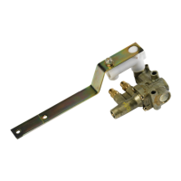
Mounting the new Height Control Valve to the designated bracket.

Attach Lever and Check Clearance

Connecting the lever arm and verifying suspension travel clearance.

Reconnect Air Lines

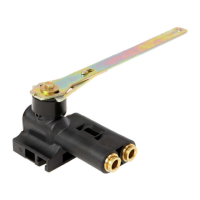
Connecting the air lines to the new HCV as per diagram.

Adjust Ride Height

Setting the valve for the correct vehicle ride height.

Tighten Nuts

Ensuring all nuts are tightened to the specified torque value.

Remove Centering Dowel

Procedure for removing the centering dowel after installation.

Troubleshooting Guide

Air Springs Flat

Diagnosing causes for air springs not inflating.

Air Springs Raise but Do Not Exhaust

Troubleshooting issues with air spring exhaust.

Air Springs Deflate When Parked

Identifying reasons for parked air spring deflation.

Suspension Will Not Maintain Proper Height

Causes for the suspension failing to hold set height.

Hard Ride

Addressing causes for an excessively harsh ride.

Unequal Ride Height

Resolving uneven ride height between sides.

HCV Test Procedure

Test Air Flow to Air Springs

Verifying air flow into air springs at 30-45 degrees.

Test Neutral Position

Confirming air flow stops at the neutral lever position.

Test Exhaust Air Flow

Checking for air exhaust from springs when lever is down.

Test Neutral Position Again

Re-confirming air flow stops at the neutral lever position.

Valve Failure Action

Action to take if the valve fails the test procedure.

Reasons to Replace the HCV

Overview

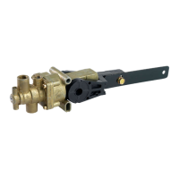
The Link 500 Series Height Control Valve (HCV), specifically the Single Port (H00500) model, is a crucial component in air suspension systems, designed to maintain a consistent and optimal ride height for vehicles. Its primary function is to regulate the air pressure within the air springs, ensuring that the suspension operates safely and efficiently. This instruction manual provides comprehensive guidance for the installation, operation, and troubleshooting of the HCV, emphasizing safety and proper maintenance practices.

Function Description

The HCV acts as the brain of the air suspension system, sensing changes in the vehicle's load and adjusting the air pressure in the air springs accordingly. When the vehicle's load increases, causing the suspension to drop, the HCV detects this change and allows compressed air to flow into the air springs, raising the vehicle back to its predetermined ride height. Conversely, when the load decreases or the vehicle needs to be lowered, the HCV releases air from the air springs, bringing the suspension back to the correct level. This continuous adjustment ensures a stable and comfortable ride, prevents bottoming out, and maintains proper vehicle geometry for optimal handling and tire wear. The single-port design indicates that it manages air flow to a single set of air springs or a single suspension circuit.

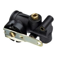
The valve operates based on the position of its lever arm, which is typically connected to the vehicle's chassis and axle via a linkage. As the suspension moves up or down, the lever arm's angle changes, signaling the HCV to either fill or exhaust air. The valve has distinct ports for air supply, exhaust, and connection to the air springs. It also features a dump pilot port, which can be used for an integral dump option, allowing for rapid deflation of the air springs when needed, such as for loading/unloading or maintenance.

Usage Features

The Link 500 Series HCV is designed for straightforward installation and operation, with several features that enhance its usability and performance:

  • Mounting Flexibility: The HCV can be attached to existing mounting brackets or utilize the enclosed brackets, offering adaptability to various vehicle configurations. It is crucial to mount the valve with the lever arm on the top side and parallel to the frame rail to ensure correct operation.
  • Adjustable Ride Height: The system allows for precise adjustment of the suspension's ride height. This is achieved by manipulating the HCV lever and following the vehicle manufacturer's specific ride height recommendations. A centering pin can be used during adjustment to ensure the valve's "dead band" (the neutral position where no air flows) is set accurately at the desired ride height.
  • Integral Dump Option: For applications requiring quick suspension deflation, the HCV supports an integral dump option. When activated, the dump pilot port connects to a 3-way selector valve, allowing for rapid air release from the air springs. It is critical to ensure that the selector system is always vented to the atmosphere when not actively dumping air to prevent valve centering issues. If the integral dump option is not used, the dump pilot port vent must remain open.
  • Robust Design: The valve is built to withstand the demanding conditions of vehicle operation. Proper tightening of fasteners to the specified torque values (60-80 in-lbs) is essential for maintaining the performance and safety of the suspension system.
  • Troubleshooting Guide: The manual includes a comprehensive troubleshooting guide that helps users diagnose common issues such as flat air springs, air springs raising to full height but not exhausting, air springs deflating when parked, suspension not maintaining proper height, hard ride, and unequal ride height. This guide links specific problems to possible causes like obstructed air lines, insufficient air pressure, defective pressure protection valves, or issues with the HCV itself.
  • HCV Test Procedure: A detailed test procedure is provided to verify the functionality of the HCV. This involves rotating the lever through its full range (up, neutral, down) and observing the air flow into and out of the air springs. This procedure helps confirm if the valve is correctly filling, exhausting, and stopping air flow as expected, aiding in quick diagnosis of a faulty valve.

Maintenance Features

While the Link 500 Series HCV is designed for durability, proper maintenance and attention to its condition are vital for long-term performance and safety:

  • Regular Inspection: Periodically checking the air lines for obstructions and leaks is crucial. Air leaks in the system can lead to various suspension problems, including deflation and inability to maintain proper height. Soapy water can be used to identify leaks in air lines and connections.
  • Lever and Linkage Check: It's important to regularly inspect the valve lever and its linkage for any signs of interference or "straight lining" throughout the entire suspension travel. Any obstruction can impede the valve's ability to accurately sense and respond to changes in ride height.
  • Fastener Torque Verification: Over time, vibrations and operational stresses can loosen fasteners. Regularly verifying that all nuts are tightened to the specified torque values (60-80 in-lbs) is a key maintenance practice to ensure the valve remains securely mounted and functions correctly.
  • Prompt Replacement of Damaged Components: The manual emphasizes that damaged components should be returned to Link with a pre-arranged Returned Materials Authorization (RMA) number. This ensures that any faulty parts are replaced under warranty conditions, if applicable, and helps maintain the integrity of the suspension system.
  • Reasons for HCV Replacement: The manual clearly outlines the conditions under which the HCV should be replaced: if it fails the prescribed test procedure, if air leaks from the HCV itself, or if the HCV is physically damaged. This guidance helps users make informed decisions about when a repair is no longer viable and a replacement is necessary to restore optimal suspension performance.
  • Safety Precautions: Throughout the manual, safety symbols (DANGER, WARNING, CAUTION, NOTICE) highlight potential hazards and provide instructions to prevent injury or property damage. Wearing appropriate personal protective equipment (gloves, eyeglasses, ear protection) when handling parts and working with pressurized air lines is strongly advised, as air lines can blow debris.

By adhering to these installation, usage, and maintenance guidelines, users can ensure the Link 500 Series Height Control Valve operates effectively, contributing to a safe, stable, and comfortable ride for their vehicles.

Link 500 Series Specifications

General IconGeneral
Product TypeControl Unit
Input Voltage24V DC
Output Voltage24V DC
Operating Temperature-20°C to +60°C
Protection ClassIP20

Related product manuals