P
Patrick ThompsonJul 29, 2025
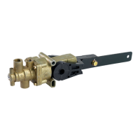
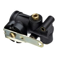
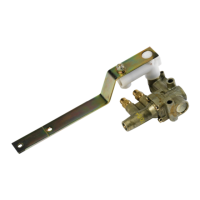
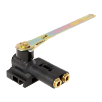
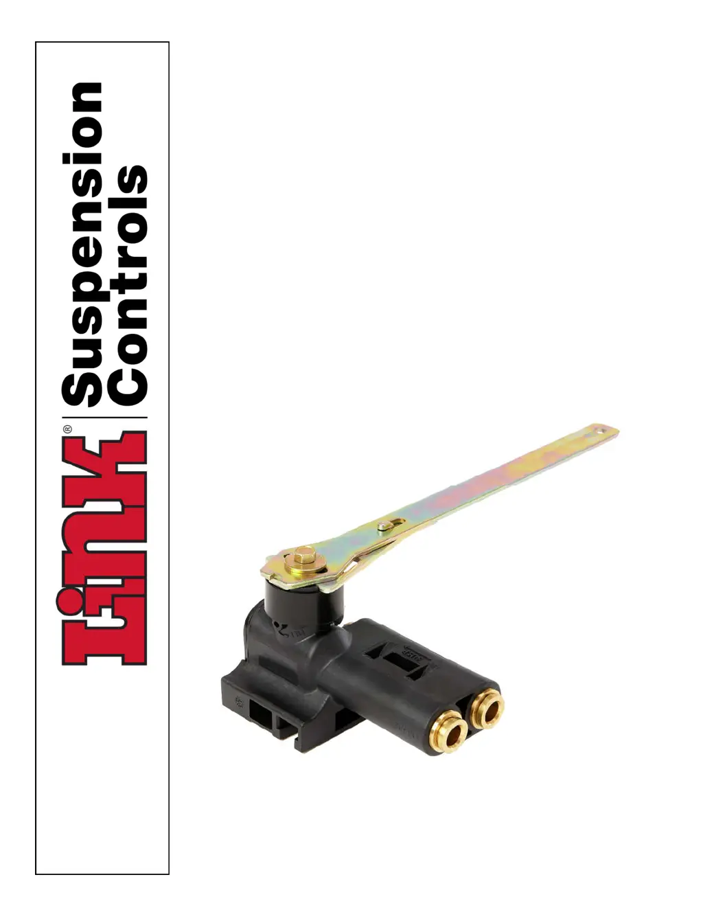
Why Link 1500 suspension will not maintain proper height?
- AAlice LeeJul 29, 2025
If the suspension of your Link Control Unit isn't maintaining the proper height, it could be due to an obstructed air line or a defective HCV. Check if the ride height is out of adjustment.