3
8. ASSEMBLE 1500 SERIES VALVE
8.1
Install the correct lever onto the valve. The lever can be
mounted in one of four directions.
8.2
Tighten screw to 50-60 in-lbs.
8.3
Install mounting studs into the T-slots. Use a hammer
to tap square head into the T-slot if needed.
9. INSTALL 1500 SERIES HCV
9.1
Remove old height control valve and note the hoses
and ports.
9.2
Attach the 1500 Series Valve to mounting bracket and
tighten nuts to 60 – 80 in lbs.
9.3
Examine the end of each tube prior to insertion and trim
the end as necessary to get a clean, 90
o
cut.
9.4
Attach hoses into the proper ports by pushing the tubes
into the push-to-connect (PTC) fittings. Use the plug
and 90
o
stem fitting included in this kit if necessary.
Make sure tubing does not interfere with lever rotation.
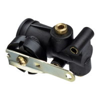
WHEN CAP DE-
TAIL IS ON THIS
SIDE OF THE
VALVE THE FILL/
EXHAUST WILL
BE IN THIS ORI-
ENTATION
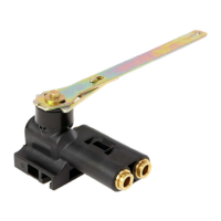
WHEN CAP DE-
TAIL IS ON THIS
SIDE OF THE
VALVE THE FILL/
EXHAUST WILL
BE IN THIS ORI-
ENTATION
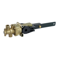
Figure 2.
SUSPENSION PORT
TORQUE TO 50-60 in libs
SUSPENSION PORT
EXHAUST PORT
SUPPLY PORT
1/4-20 MOUNTING BOLT
TORQUE NUTS TO 60-80 in lbs
MOUNTING BOLTS
(2 INCLUDED) CAN BE MOUNTED IN
ANY OF 4 CORNER POSITIONS
Figure 1.
6. DETERMINE MOUNTING AND VALVE
ORIENTATION
6.1
Hold 1500 Series Valve next to height control valve to
be replaced and determine mounting orientation of the
1500 Series Valve for best hose routings.
6.2
NOTE: The supply port must be horizontal or pointing
up.
6.3
Determine location of the 2 mounting studs and proper
lever length.
7. DETERMINE FILL AND EXHAUST
ORIENTATION
7.1
Each side of the 1500 Series Valve has arrows pointing
toward the fill and exhaust directions.
7.2
Align the U-shaped cap detail with the fill/exhaust ar-
rows that correspond with the fill and exhaust move-
ments on the lever. Rotating the cap 180
o
will result in
the opposite fill and exhaust lever movement.
“U” SHPAED
CAP DETAIL
“U” SHPAED
CAP DETAIL
 Loading...