2
IMPORTANT: IT IS IMPORTANT THAT THE ENTIRE IN-
STALLATION INSTRUCTIONS BE READ THOROUGHLY
BEFORE PROCEEDING WITH THE INSTALLATION.
1. INTRODUCTION
Thank you for choosing a Link Suspension Control. We
want to help you get the best results from this height
control valve and to operate it safely. This instruction
contains information to assist in the installation of the
Height Control Valve. This instruction is intended solely
for use with this product.
All information in this instruction is based on the latest
information available at the time of printing. Link Manu-
facturing reserves the right to change its products or
manuals at any time without notice.
Damaged components should be returned to Link with
a pre-arranged Returned Materials Authorization (RMA)
number through the Customer Service Department.
The damaged component may then be replaced if in
compliance with warranty conditions.
2. SAFETY SYMBOLS, TORQUE SYMBOL,
and NOTES
3. SAFE WORKING PRACTICES
When handling parts, wear appropriate gloves, eye-
glasses, ear protection, and other safety equipment.
Proper tightening of fasteners is important to the perfor-
mance and safety of the suspension. Follow all torque
specifications throughout the instructions.
4. SAFE WORKING PRACTICES
4.1
Air lines are pressurized and may blow debris, USE
EYE PROTECTION.
DANGER indicates a hazardous
situation which if not avoided, will
result in death or serious injury.
WARNING indicates a potentially
hazardous situation which, if not
avoided, could result in death or
serious injury.
CAUTION indicates a potentially
hazardous situation which, if not
avoided, could result in minor or
moderate injury.
NOTICE indicates a potentially
hazardous situation which, if not
avoided, may result in property
damage.
TORQUE indicates named fasteners
are to be tightened to a specified
torque value.
NOTE:
A Note provides information or
suggestions that help you correctly
perform a task.
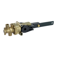
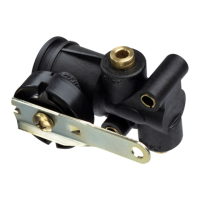
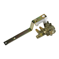
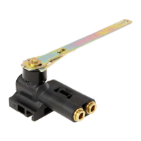
Figure 1.
ITEM NO DESCRIPTION QTY
1 8” ADJUSTABLE LEVER 1
2 7” ADJUSTABLE LEVER 1
3 7” STRAIGHT LEVER 1
4 3/8” PTC PLUG 1
5 MOUNTING BOLT 2
6 3/8” PTC 90
o
STEM FITTING 1
7 1/4-20 LOCK NUT 2
8 WASHER 2
9 INSTRUCTION SHEET 1
5. PARTS INCLUDED
 Loading...