4
10.
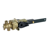
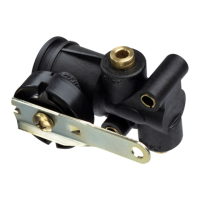
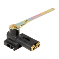
1500 SERIES VALVE
TEST PROCEDURE
10.1
NOTE: 90 PSI minimum supply and pilot pressure
10.2
Rotate lever in the fill direction and fill air springs.
10.3
Rotate lever in the exhaust direction and exhaust air.
NOTE: if fill and exhaust modes are backwards, ex-
haust air from suspension, loosen lever screw enough
to separate lever from valve. Rotate lever 180
o
, reseat
in cross pattern of valve and retighten lever screw. Ro-
tate lever 180
o
to original position. Retest fill and ex-
haust modes.
11. RIDE HEIGHT ADJUSTMENT
11.1
Manually air up the valve to ride height. Check the vehi-
cle manufacturer’s ride height recommendations for
correct height.
11.2
Reconnect linkage to end of lever.
11.3
Measure ride height.
11.4
Readjust ride height by loosening the lever screw
enough to rotate the bottom to fill or exhaust the air
until the correct ride height is attained.
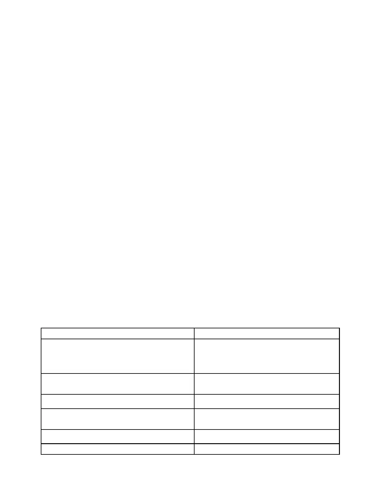
PROBLEM POSSIBLE CAUSE
Air springs flat
Obstructed air line
Insufficient air pressure to suspension
Defective Pressure Protection Valve
Defective HCV (see test procedure)
Air leak in system
Air springs raise to full height but do not exhaust
Obstructed air line
Supply line installed in suspension port
Defective HCV (see test procedure)
Air springs deflate when parked
Leak in air system (check with soapy water)
Defective HCV (see test procedure)
Suspension will not maintain proper height
Obstructed air line
Ride height out of adjustment
Defective HCV (see test procedure)
Hard ride
Ride height out of adjustment (readjust per
vehicle service manual)
Ride height unequal side to side for (2) valve system Reset ride height on each side
11.5
Tighten the lever screw to 50 – 60 in lbs.
11.6
Double check the ride height measurement by dumping
the suspension and allowing the 1500 Series Valve to
air up to ride height (Disconnect and reconnect the link-
age).
11.6
Remeasure ride height and adjust if necessary.
12. HCV INSTALLATION NOTES
12.1
Optimal lever angle for full up or down travel is be-
tween 20
o
and 45
o
12.2
Mount HCV with supply port horizontal or pointing up
13. HCV TEST PROCEDURE
13.1
1. With a minimum of 90 psi at the supply port, rotate
the lever up (as indicated on the side of the valve)
30° to 45°. Air should flow into the air springs.
2. Rotate the lever to the neutral position. Air flow
should stop.
3. Rotate the lever down 30
°
to 45
°
. Air should ex-
haust from the air springs.
4. Rotate the lever to the neutral position. Air flow
should stop.
5. If a valve fails to flow air or shut off as specified,
replace with a new one.
14. REASONS TO REPLACE THE HCV
1. HCV did not pass the test procedure
2. Air leaks form the HCV
3.
HCV is damaged
15. TROUBLESHOOTING
 Loading...