This document describes the LK-CP64X Control Panel (6A), a versatile device designed for controlling 24VDC motors used in window openers, curtain motors, and door openers.
Function Description
The LK-CP64X control panel serves as a central unit for managing various motor-driven applications. It features a built-in 24VDC/6A switching power supply and accepts a wide voltage input of 100-240VAC. The panel is available in single, dual, and four-channel output configurations (LK-CP641, LK-CP642, LK-CP644, respectively).
Key functionalities include:
- Motor Control: Direct control of 24VDC motors for opening and closing operations.
- Power Management: Integrated power supply for efficient operation.
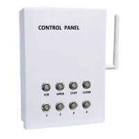
- User Interface: Features power indicator/reset, Open/Stop/Close, and channel selection buttons, all with backlight for ease of use.
- Cascade Control: Can be cascaded with LK-CP6/CP7/CP8 and LK-FP3 units to achieve advanced zone and group control of windows. It can act as a master, slave, or a dual-role controller.
- External Input Handling: Capable of processing signals from various external sources including manual switches, remote controls, timers, and environmental sensors (smoke/gas, rain, temperature/humidity).
- Fire Feedback: Provides an output fire feedback signal to a fire center.
- Remote Compatibility: Compatible with all LinkAYL remotes.
- Operating Modes: Supports both inching mode and continued-run mode, which are settable.
- Stroke Memory: Includes a stroke memory function to set and recall specific opening strokes for motors.
Important Technical Specifications
General:
- Power (W): 144W
- Vin (VAC): 100-240V
- Vout (VDC): 24V
- Frequency: 433.92MHz
- Dimensions (mm): 174 x 127 x 51mm
Model-Specific Channels:
- LK-CP641: 1 Channel
- LK-CP642: 2 Channels
- LK-CP644: 4 Channels
Application Compatibility:
- LK-SCE-D: 6 units
- LK-LCD: 4 units
- LK-TC: 2 units
- LK-L36A/B, LK-L38AT/AF: 4 units each
LED/KEY Indicators:
- L1/K1 (Blue): AC power, Reset (On/Off)
- L2/K2 (Green): Open (On/Off/Flash)
- L3/K3 (Red): Stop (On/Off)
- L4/K4 (Yellow): Close (On/Off)
- L5/K5 (Blue): Channel 1 (On/Off)
- L6/K6 (Blue): Channel 2 (On/Off)
- L7/K7 (Blue): Channel 3 (On/Off)
- L8/K8 (Blue): Channel 4 (On/Off)
Terminal Connections:
- Power: L (AC live), N (AC null), E (AC earth), V+ (24VDC input positive), V- (24VDC input negative).
- Motor: M+ (24VDC motor positive), M- (24VDC motor negative).
- Manual Switch: MU (Manual switch up), MS (Manual switch stop), MD (Manual switch down), MG (Manual switch GND).
- Sensors/Control: FSO (Fire signal output), FOO (Fire output NO), FOC (Fire output NC), 24V (24VDC+ output), FSI (Fire signal input), COM (Sensor COM), S+ (Slave control up), S- (Slave control down), 12V (DC12V+ output), WRD (Rain sensor down), T/H (T/H signal).
Usage Features
Manual Control:
- Upon power-on, all LEDs light for 1 second, then turn off, with the power indicator LED (L1) remaining on.
- Pressing the reset button lights all LEDs for 1 second, then turns off, indicating a successful reset.
- L2 flashes rapidly when the controller receives a fire signal.
- External manual switches function identically to the controller panel switches.
- Maximum motor running time is 5 minutes.
Group Control:
- By default, L1 is on, and other LEDs are off, indicating group control status.
- Pressing UP opens windows (LED on for 5 seconds), DOWN closes windows (LED on for 5 seconds), and STOP halts motors (LED on for 1 second).
Channel Control:
- Pressing channel selection keys illuminates the corresponding LED.
- If no operation occurs within 10 seconds after channel selection, the LED turns off, and the channel becomes unselected.
- During opening/closing, other channels can be selected to drive additional windows.
Cascaded Control:
- The controller can operate as a master, slave, or both.
- As a master, it connects to motors or slave controllers.
- As a slave, S+ and S- terminals connect to the master's M+ and M- terminals to receive instructions or operate independently.
- In a dual role, it can be controlled by a higher-level controller while also driving motors or lower-level controllers.
- It processes all external signals (manual switch, remote, sensors).
- When cascaded, slave controllers must not use inching mode if the master controller is connected to an external sensor (e.g., smoke sensor) to prevent brief window openings.
Remote Control:
- Uses 433MHz learning code and can store up to 10 transmission codes.
- Defaults to multiple-channel control; single-channel control operates similarly.
Matching Code:
- Power on the controller, select desired channel(s) (any combination of 1-4).
- Press STOP button on the controller for 5 seconds (LED flashes 3 times, then off).
- Select the desired channel on the remote.
- Press UP on the remote within 15 seconds (LED flashes 3 times, then off).
- Code matched successfully.
Clearing Codes:
- Single Code: Power on, press STOP key for 5 seconds (LED flashes 3 times, then off), press DOWN on remote within 15 seconds (LED flashes 3 times, then off).
- All Codes: Power on, press STOP/DOWN button for 5 seconds (LED flashes 3 times, then off). All codes are deleted.
Signal Control and Priority:
- Priority 1 (Manual Signal): Panel buttons, manual switch, remote, master controller.
- Priority 2 (Fire Signal): Smoke sensor, gas detector.
- Priority 3 (W/R Signal): Wired wind rain sensor.
- Priority 4 (T/H Signal): Temperature sensor, humidity sensor.
- Higher priority signals override lower priority ones.
Reset and Shielding:
- After a manual signal, the controller receives input in real-time.
- After a fire signal, the controller immediately shields all other input signals and must be manually reset by pressing K1.
- After a wired rain sensor signal, the controller shields lower priority signals, only accepting higher priority signals until reset or manual signal.
- After a T&H sensor signal, the controller enters a reset state.
- If no T&H sensor is connected, the T/H port must be shielded (option switch to "Y" position).
Stroke Memory:
- Allows setting and memorizing the opening stroke; triggering the window opening signal once will run the motor to the memorized stroke.
- Default stroke runs for 5 minutes.
- Setting Stroke: Press both UP/DOWN buttons for 3 seconds (LEDs flash 3 times, then off). Select channels, determine stroke using manual/remote keys. Press UP/DOWN again for 3 seconds (LEDs flash 5 times, then off) to save.
- If no operation for 15 seconds during setting, it exits automatically, retaining the last memorized stroke.
- Stroke memory can be reset by pressing STOP/DOWN buttons for 3 seconds (LEDs flash 3 times, then off), restoring default 5-minute output.
- Master/slave controllers will run their own memorized stroke; slave runs the shorter stroke when receiving cascade signal.
- Memorized stroke is retained even after power down or reset.
- Closing the window defaults to 5 minutes output time.
Control Modes:
- Inching Mode: Press UP/DOWN for less than 1.5 seconds to stop motor; press for more than 1.5 seconds for continuous run.
- Continued-Run Mode (Default): Press UP/DOWN for less than 1.5 seconds for continuous run; press for more than 1.5 seconds to stop motor.
- Manual buttons, manual switch, remote, and cascade signals can operate in inching mode.
- To switch to continued-run mode from inching mode, press both UP and STOP buttons for 5 seconds (LEDs flash 3 times, then off). Repeat to switch back to inching mode.
Maintenance Features
Installation Instructions (Important for proper function and longevity):
- Read instructions carefully before installation.
- Installation must comply with local electricity specifications and be performed by a professional.
- Main power must be cut off before wiring.
- Total additive maximum output power must not exceed the controller's rated power.
- Avoid metal objects touching or covering the controller to prevent interference with remote control signals.
- Maximum wireless transmission distance is 50 meters or more in open conditions.
- Maintain specific distances: >1.5 meters from ground, >0.3 meters from ceiling, >1.5 meters from motor.
- Avoid static interference and damage to electronic components.
- Use soft wire and cable; ensure cable carrier is not affected by longitudinal tension.
- External sensors must be compatible with this controller.
- Non-professionals should not disassemble the controller. Contact local dealer for abnormal functions.