Rev: 08.30.21 Page 5 CCD-0004385
B
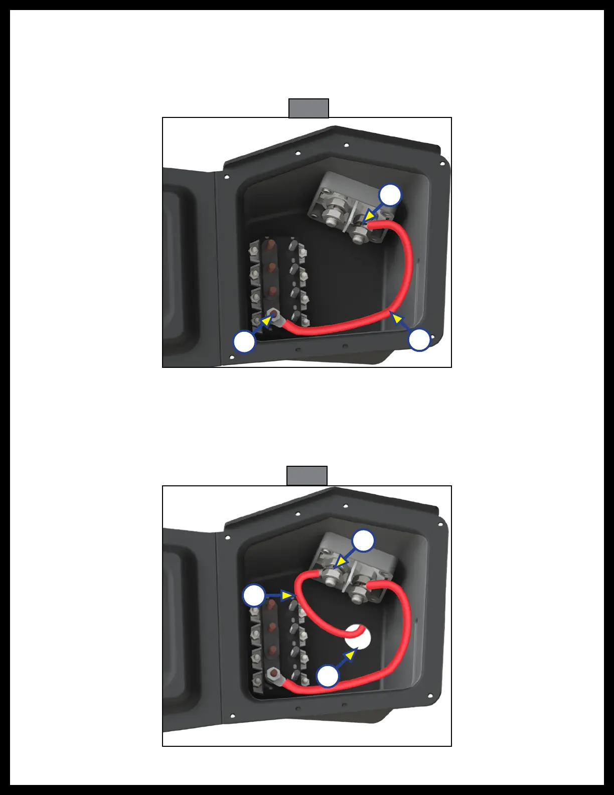
Fig. 3
2. Install busbars (Fig. 2A) onto the copper posts of circuit breakers (Fig. 2B) if necessary.
3. Connect the large terminal of the shorter red output cable (Fig. 3A) to one post of the battery
disconnect switch (Fig. 3B) and the other, smaller terminal to a copper post of the circuit
breakers (Fig. 3C).
Note: Torque the nuts on the battery disconnect switch post to 18.44 ft-lbs (25 N-m).
C
A
4. Drill a penetration hole in the side door housing for the battery input cable (Fig. 4A).
Note: Hole should be a minimum 3/4" diameter and should be made in a location for convenient routing
and connection of the longer red input cable.
5. Connect one end of the longer red input cable (Fig. 4B) to the other terminal of the battery disconnect
switch (Fig. 4C) and route cable out of side door housing hole (Fig. 4A).
Fig. 4
A
B
C