Do you have a question about the Lippert Components 13398-C1 and is the answer not in the manual?
Details the primary components of the slide system, including motors and controllers.
Explains how to correctly connect the motor wiring harnesses to the control board.
Describes the process for connecting the extend and retract wall switches to the control board.
Details the power requirements and connection methods for the control board.
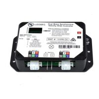
Provides a visual overview and identification of key components on the control board.
Guides users on how to enter and operate manual mode for jogging individual motors.
Outlines the procedure for adjusting the stall force to ensure proper room sealing and operation.
Lists and explains the various error codes indicated by the controller's LEDs for diagnostics.
Explains how to use motor direction switches to correct motor movement or switch wiring.
Presents a wiring schematic illustrating the system's electrical connections.
Procedure for manually operating the slide when the unit fails to function electrically.
Step-by-step instructions for disengaging the motors for manual movement or maintenance.
Detailed guide on how to replace a faulty motor in the slide mechanism.
Instructions for replacing the entire slide mechanism assembly.
A visual flowchart to diagnose and resolve common slide system issues.
Guidance on inspecting and replacing fuses for the slide control system.
How to identify and remove physical obstructions affecting slide operation.
Reference for understanding and resolving issues indicated by controller error codes.
Troubleshooting steps for problems caused by low battery voltage.
Diagnosing and addressing issues where only one side of the slide moves.
Procedure to manually assist the non-moving side of the slide.
Checking if the non-moving slide side can be moved by hand, indicating motor issues.
Verifying if the slide can be moved manually after disengaging the motors.
Instructions for checking and clearing debris from the slide's gear racks.
Troubleshooting based on the status LEDs' behavior when the direction switch is actuated.
Guidance on increasing motor amperage (stall force) when necessary for room cycling.
| Brand | Lippert Components |
|---|---|
| Model | 13398-C1 |
| Category | Controller |
| Language | English |