EasyManua.ls Logo

Lippert Components 13398-C2 - User Manual

Lippert Components 13398-C2
16 pages
Print Icon
To Next Page IconTo Next Page
Loading...
Schwintek in-wall Slideout SyStem
operation and Service manual
LIPPERTCOMPONENTS, INC.
Contents
I. Controls
1-1 System components 1
1-1A versions C1 & C2 2
1-2 Motor wiring harness connections 3
1-3 Extend and retract switch connections 3
1-4 Power to board 4
1-5 Board overview 4
1-6 Manual mode -jog 5
1-7 Manual mode -stall force calibration 5
1-8 Error codes 5
1-9 Motor direction switches 7
1-10 System schematic 7
II. Motors
2-1 Manual override 8
2-2 Motor disengagement 8
2-3 Motor replacement 10
2-4 Slide mechanism replacement 13
III. Troubleshooting
3-1Troubleshootingowchart 15
I. CONTROLS - VERSIONS B, C, C1 & C2
1-1 System components
motor 1 slide controller motor 2
motor wiring harnesses
Rev-C motor and Controller components install exactly as Rev-B. However, Rev-B
components are not to be used with Rev-C components. Rev-C2 components are shown in Fig. 1.
REV-C Motor
REV-C Controller
Fig. 1
reve030911

Other manuals for Lippert Components 13398-C2

Question and Answer IconNeed help?

Do you have a question about the Lippert Components 13398-C2 and is the answer not in the manual?

Lippert Components 13398-C2 Specifications

General IconGeneral
BrandLippert Components
Model13398-C2
CategoryController
LanguageEnglish

Summary

I. Controls

1-6 Manual mode -jog

Procedure for entering manual mode to jog individual motors for precise positioning.

1-7 Manual mode -stall force calibration

Steps to calibrate the stall force to ensure proper room sealing and prevent motor overload.

1-8 Error codes

List and explanation of error codes indicated by LED patterns on the control board.

1-1 A.3 Stall Threshold Calibration Mode

Procedure for adjusting the stall threshold using a potentiometer and saving the setting.

1-1 A.4 Override Mode

Details on using override mode for manual room movement and safety features active in this mode.

II. Motors

2-2 Motor disengagement

Step-by-step guide to disengage motors for manual movement or maintenance.

2-3 Motor replacement

Detailed instructions for replacing a faulty motor, including coupler alignment.

III. Troubleshooting

3-1 Trouble shooting flow chart

Visual flowchart to diagnose and resolve common slide unit operational issues.

3-4 Error Codes

Reference for understanding and addressing error codes reported by the slide controller.
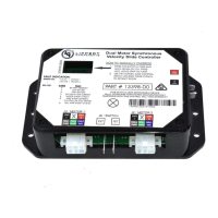
Related product manuals