Rev: 05.24.2016
Page 5
Slim Rack Slide-out Manual
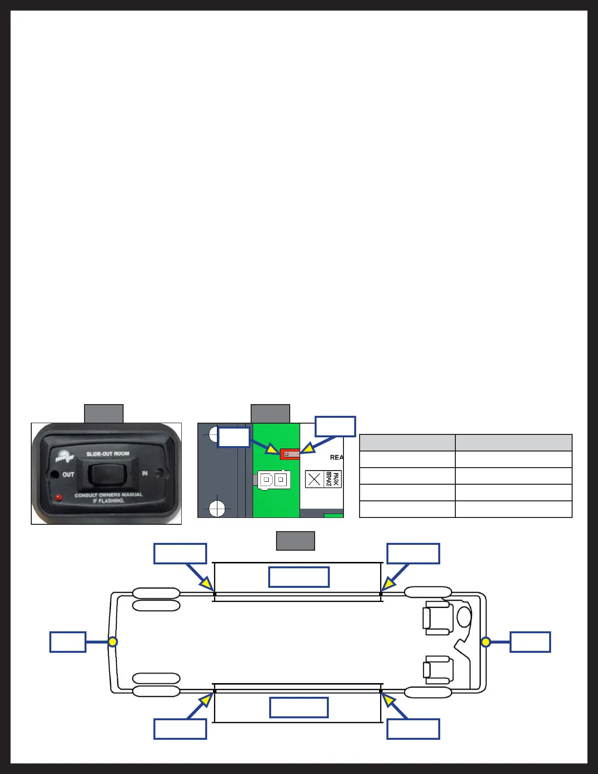
B. 1510000276 control. With the switch in the left position (as shown) the control will be in bypass
(not looking for a park brake input signal). With the switch in the right position the control will be
looking for a park brake signal input.
6. If using the park brake feature, route the park brake input harness from the park brake signal source to
the control box.
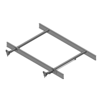
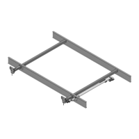
NOTE: It is important that the slide-out motors be plugged in to the proper receptacle at the control box.
See (Fig. 7) below for proper slide-out motor designation. Failure to properly connect the motors to
the control will result in problems for future troubleshooting. (The control will identify the incorrect
motor during a fault).
7. Route and attach the proper gauge wire from the control to the 12V DC battery. It is recommended
that this circuit be protected with a 30 amp fuse. Wire must be sized so that a minimum of 12.5 VDC is
measured at the control while under load.
Fig. 5 Fig. 6
Fig. 7
Roadside
Curbside
Rear Front
Motor 2
Motor 2 Motor 1
Motor 1
Wire Gauge Maximum Length
16 10 feet
14 15 feet
12 25 feet
10 40 feet
Left
Right
 Loading...