Do you have a question about the Lippert Components ELECTRIC SLIDEOUT SYSTEM and is the answer not in the manual?
Critical safety warnings regarding the intended use and potential hazards of the slideout system.
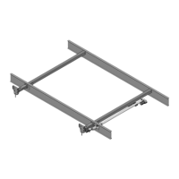
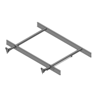
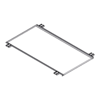
Explains the Lippert Electric Slideout System as a rack & pinion guide system with an electric ball screw actuator.
Guidelines to follow before operating the Lippert Electric Slideout System for safe and proper function.
Focuses on battery maintenance, checking connections, and ground integrity for optimal performance.
Recommendations for lubricating seals, checking for damage, and periodic actuation.
Crucial safety precautions to observe during the operation of the slideout room.
Step-by-step instructions for extending the slideout room, including switch operation.
Step-by-step instructions for retracting the slideout room, including switch operation.
Critical warnings about disconnecting the battery and potential damage during manual operation.
Instructions on how to manually extend or retract the slideout room using a crank handle.
Steps to loosen bolts and position the room horizontally using a prying device.
Steps to loosen bolts and adjust the room height using a vertical adjustment bolt.
Procedure for adjusting the stop can and nuts to ensure the room seals correctly when retracted.
Procedure for adjusting nuts to ensure the room seals correctly when extended.
Procedure to adjust synchronizing brackets to ensure both sides of the room travel the same distance.
Step-by-step instructions for disconnecting and removing the actuator from the slideout system.
Instructions for replacing the actuator, reversing the removal steps.
Explains how chassis, room, coach, and slideout system components affect troubleshooting.
Provides advice on slide tube cleanliness, checking battery, wiring, and potential impact of changes.
Lists causes and corrective actions for when the slideout room fails to move upon switch activation.
Addresses issues where the motor runs but the room does not move, checking actuator attachment.
Identifies causes like low battery, poor ground, or room bind for slow movement.
Solutions for when the room stops moving during extension or retraction.
Provides notes on switch wiring, gear stripping, and room timing/synchronization.
Steps to test for 12V DC at the switch and motor using a voltmeter.
States the motor is not field serviceable and emphasizes checking wiring and connections.
Visual representation of the electrical connections for the slideout system, including battery, switch, and motor.
Lists the necessary information to provide when ordering replacement parts for the slideout system.
States that unauthorized modifications may void the warranty.
| Category | Motorhomes |
|---|---|
| Voltage | 12V DC |
| Maximum Load Capacity | Varies by model |
| Type | Electric Slide-Out System |
| Control Type | Switch or Remote Control |
| Compatibility | Compatible with various motorhome models |