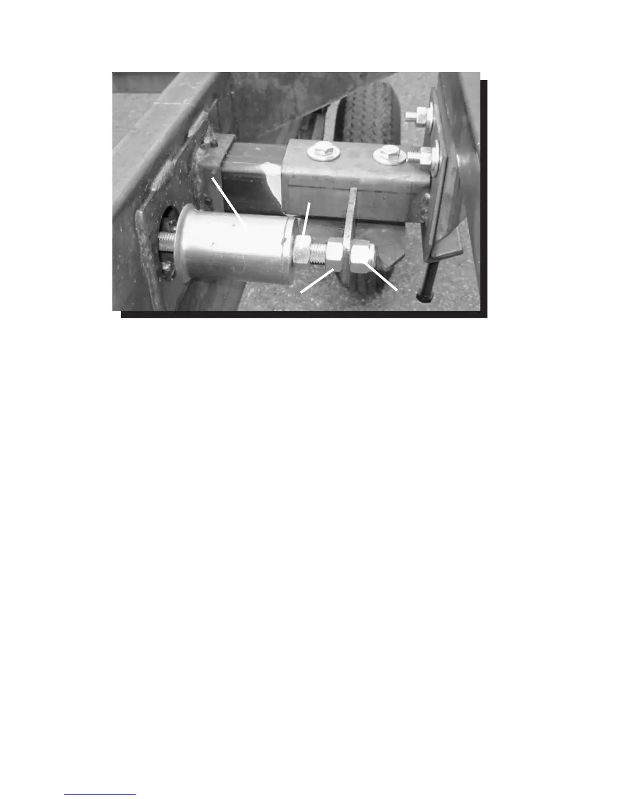
Stop Can
Jam Nut-1
Nylock Nut
Jam Nut-2
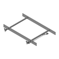
Adjusting room so it seals in the IN position
1. Locate actuator coming through the frame
2. On the end of the actuator there is a threaded shaft
mounted to the drive bracket with 3 nuts and a stop can.
3. Loosen the ¾” nut (Jam Nut-1) on the outside of the stop
can.
4. Screw the can out or in, and then tighten down the nut – this
will change the location of your seal going to the “in
position”.
Adjusting room so it seals in the OUT position
1. Locate actuator coming through the frame.
2. On the end of the actuator there is a threaded shaft mounted
to the bracket with 3 nuts and a stop can.
3. Move one of the 1” nuts (Jam Nut-2 or Nylock Nut) one way
or the other– this will change the location of your seal going
to the “out position”.
4. Make sure all nuts are tight.
MECHANICAL ROOM ADJUSTMENT-CONT.
Fig.8
11