Rev: 05.24.2016
Page 4
Slim Rack Slide-out Manual
3. Lift the slide room box into the coach opening and push in until the mounting flange meets the
exterior wall.
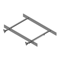
4. Verify the weight of the room is supported by the floor rollers and not the slide-out mechanism (Fig. 2).
NOTE: If the room is not completely supported by the floor rollers, you will hear a slight “popping” sound
as the room settles on to the rollers. This is normal, and there is nothing wrong with the system or
the install.
5. Secure the mounting flanges to the unit’s side wall with button or pan head #10 screws torqued to 40-
50 in-lbs.
Alternate Install for Vertical Channel Assemblies with Two Flanges
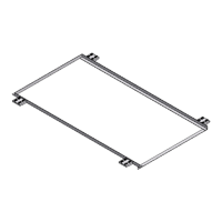
After steps 1-2 above are complete, it will be necessary to remove the inner flange (Fig. 4) from each side of
the vertical channel assemblies before lifting the room into position. Once room is in position, reinstall the
removed flanges. Installation of the vertical channel assembly is now complete.
Electrical Components
1. Mount the controller in a clean and dry, weather tight location that will keep it from being damaged,
but is easily accessible for service. The controller is not waterproof.
2. Determine location to mount the rocker switch (Fig. 5). The location needs to be in view of slide-out
room and have minimum depth of 1” inside the wall.
3. Route and attach the harness to where the rocker switch will be mounted, and mount the rocker
switch with 2 screws.
4. Label the motor leads at both ends to aid in connections at the control box and motors. Route the
motor/sensor harnesses from the slide-out room motors to the control box.
5. Set park brake signal input (Fig. 6):
A. 1510000236 control. With the switch in the left position (as shown) the control will be looking for
a park brake signal input. With the switch in the right position the control will be in bypass (not
looking for a park brake input signal).
Fig. 2
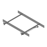
Fig. 3
Fig. 4
Floor Roller (Not Supplied)
 Loading...