6
lci1.com 574-537-8900 Rev: 08.14.20
Schwintek
Motorized TV Lift
Installation and Owner’s Manual
(For Aftermarket Applications)
CCD-0002647
Setting the Extend and Retract Limits
1. To set the lower electronic stop, press and hold the
switch’s RETRACT button (Fig.10B) to lower the TV
into the desired position, then press the control’s white
Conguration button once (Fig.8A).
2. To set the raised electronic stop, press and hold
the switch’s EXTEND button (Fig.10A) to raise the TV
into the desired position, then press the control’s white
Conguration button once.
3. Test the receiver’s programming by lowering and raising
(retracting and extending) the TV.
Sync Remote, if Included
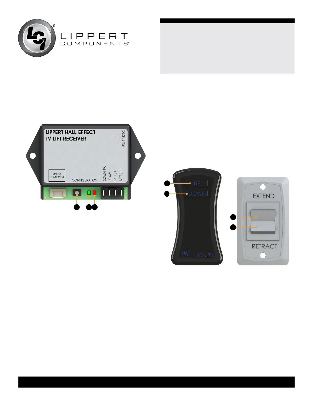
1. Locate white Conguration button (Fig.8A).
2. Press the button two times and hold on the third time.
3. The green LED (Fig.8B) and the red LED (Fig.6C) will
alternately ash.
4. Hit any button on the remote (Fig.7).
5. The green LED (Fig.6B) and the red LED (Fig.6C) will ash
at the same time, then stop.
6. The remote is now synced.
Operation
1. To raise the TV, press and release the switch’s UP
button on the remote (Fig.9A) or press and release the
EXTEND button on the switch (Fig.10A) until the TV lift is
fully raised into position.
2. To lower the TV, press and hold the switch’s DOWN
button on the remote (Fig.9B) or press and hold the
RETRACT button on the switch (Fig.10B) until the TV
is fully lowered into the cabinet.
NOTE: For safety purposes, the switch will need to be held
until lowered to the preset stop limit.
TV and Rack Removal from Lift
To remove the TV and rack out of the lift unit,
do as follows:
1. Press and hold the control’s white CONFIGURATION
button (Fig.8A) for ve seconds.
NOTE: The control’s red LED (Fig.8C) will light up solid and
the green LED (Fig.8B) will flash.
2. Press and hold the switch’s EXTEND button (Fig.10A)
until the rack and TV are fully raised so they can be
removed from the system.
Programming
To enter programming mode, press and hold the white
CONFIGURATION button (Fig.8A), located on the control,
for five seconds. The control’s green LED (Fig.8B) will flash
and its red LED (Fig.8C) will light up solid.
Fig.8
A CB
Fig.9
A
B
A
B
Fig.10