Rev: 01.24.19 Page 3 CCD-0002165
As a supplier of components to the RV industry, safety, education and customer satisfaction are our primary concerns. Should you
have any questions, please do not hesitate to contact us at (574) 537-8900 or by email at customerservice@lci1.com. Self-help tips,
technical documents, product videos and a training class schedule are available at lci1.com or by downloading the MyLCI app.
SOLERA SMART ARM™ LED LIGHTING
INSTALLATION GUIDE
TI-302
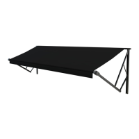
AWNINGS
Operation
NOTE: The controller (touchpad) does not need to be unlocked to control the lights.
1. Press the light button (Fig. 1C) to turn on the LED light strip. The button's green LED indicator light will
illuminate when the LED light strip is on.
2. There are three light level settings:
A. Press the light button once for the low setting or 10% illumination
B. Press the light button twice for the medium setting or 30% illumination.
C. Press the light button three times for the high setting or 100% illumination.
3. Press the light button four times to turn off the LED light strip.
NOTE: The light setting defaults to 100% illumination if turned off then on by an external light input
command, CAN bus command or if motion is detected by the IR sensor while the light setting is in
AUTO mode.
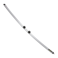
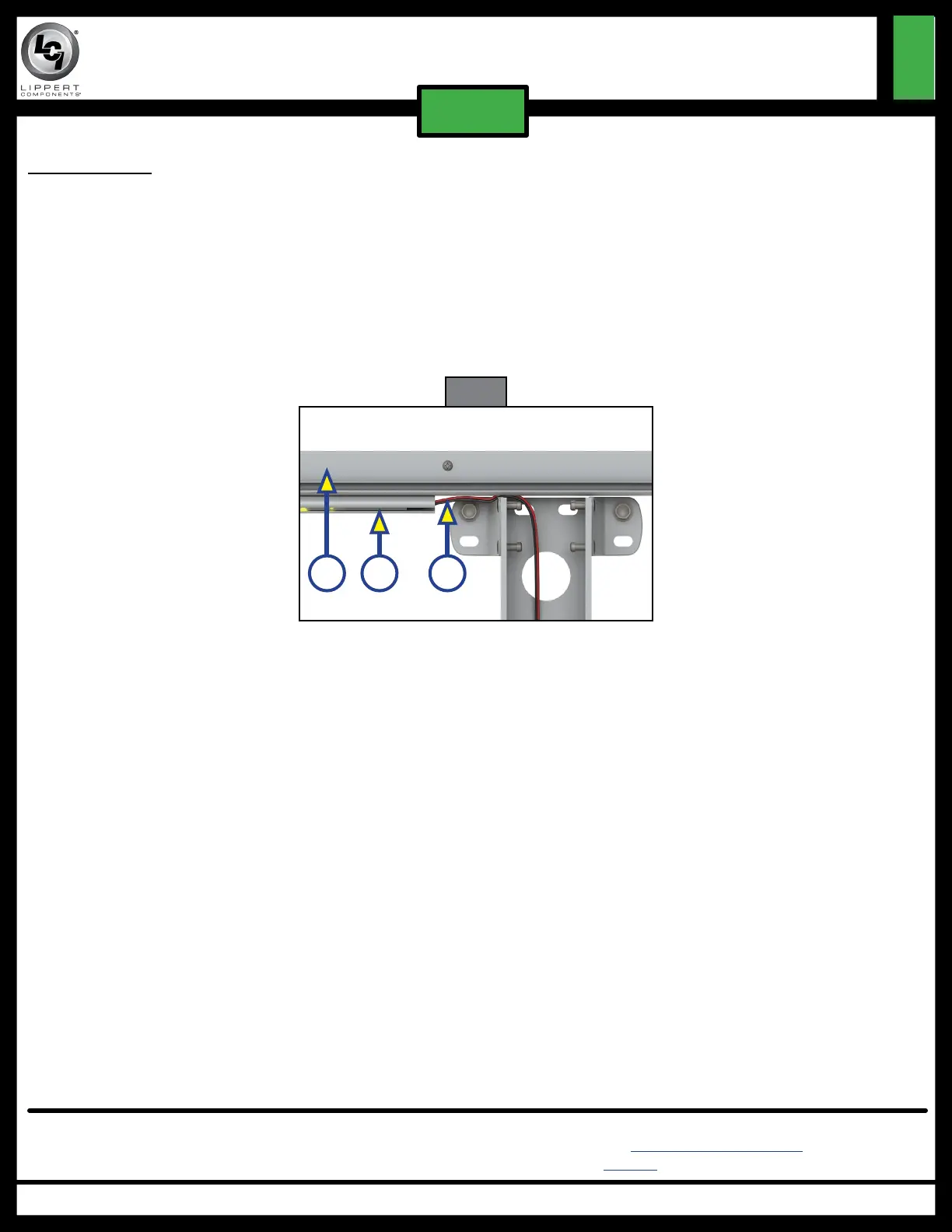
LED Light Rail
1. Seal the back of the LED light rail.
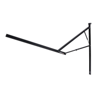
2. Mount the LED light rail (Fig. 4A) directly below the awning rail (Fig. 4B) and secure to the side of the unit.
3. Depending on top wire or bottom wire installation, remove the wire covers in the drive mount arm.
4. Route the light wire over the top of the upper brackets on the mount arm and run the light wire down
through the support arm assembly in the same manner as the motor wire (Fig. 4C).
5. Connect the red power wire from the LED to the red (LIGHT) wire in the smart arm and the black ground
wire from the LED to the white (LIGHT) wire in the smart arm.
6. Reinstall the wire covers in the drive mount arm.
Fig. 4
BA C

 Loading...