Rev: 05.22.23 Page 3 CCD-0001436
1. Verify size of door opening is correct. Door "call" size is
the required rough opening size. The actual door size will
be undersized by ½" in width and height. (i.e. 26" x 72"
door requires an opening of 26" x 72" but the actual door
size will be 25
½
" x 71
½
").
NOTE: The rough opening size tolerance is +/-
⁄
" for width
and -
¼
" on height. A rough opening of +/-
⁄
" for
the width is a Fail; +/-
¼
" or over for the width is a
Critical Fail. On Motorized door rough opening width,
¼
" can be added.
NOTE: The opening squareness measured corner to corner is
+/-
⁄
". Squareness measured +/-
⁄
is a Fail; over
¼
"
is a Critical Fail.
2. Install sealant tape around back side of the screw track
frame. Lippert recommends using putty tape or closed
cell PVC foam tape.
NOTE: Excessive putty tape or foam tape in the plunger
opening may restrict full engagement of the latching
mechanism.
3. Make sure that the door is sealed along the bottom,
either on the lip of the opening or the edge of the floor.
NOTE: The deadbolt should be disengaged at this point.
4. Set the door in the wall opening, so that the bottom edge
sets flat on the floor and the hinge side is flush against
the opening.
NOTE: If the door is offset to the latch side, the plunger may
hit the side wall framing and not engage completely.
5. Install a #8 screw in the hole nearest the bottom hinge
(Fig. 1A) and another #8 screw in the hole near the
Installation
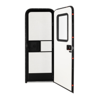
Exterior Frame Installation - Towable and Motorized
Steps 1-10 of the installation must be performed with the door assembly in the closed position. Step 11
must be performed with the door assembly in the open position.
NOTE: The door is shipped with a jig (Fig. 2A) holding the doors together to prevent deformity. Leave the
jig in place until step 10 of the instructions.
NOTE: Spacer blocks come installed in the door assembly to hold and properly space the door in the frame.
G
H
F
C
E
A
B
D
Fig. 1
bottom of the latch side (Fig. 1B).
6. Install a #8 screw in the hole near top hinge (Fig. 1C).
7. Make sure door sets evenly in the frame and that the frame on the latch side maintains a
⁄
" gap. Next,
install a #8 screw into a hole near the top of the door on the latch side (Fig. 1D).
 Loading...