M & MA Series Meters
39
Get the latest PDF manual:
https://www.lcmeter.com/resources/technical/manuals
Mobile/online version of this manual:
https://www.lcmeter.com/manuals
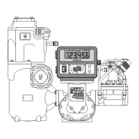
3. Position the spare displacement rotor gear between the left displacement rotor gear and
the blocking rotor gear to prevent the gears from moving. Attach the right displacement
gear washer and screw using the rotor gear wrench.
4. Keep the spare displacement rotor gear positioned by the left displacement rotor gear.
Attach the left displacement gear washer and screw using the rotor gear wrench.
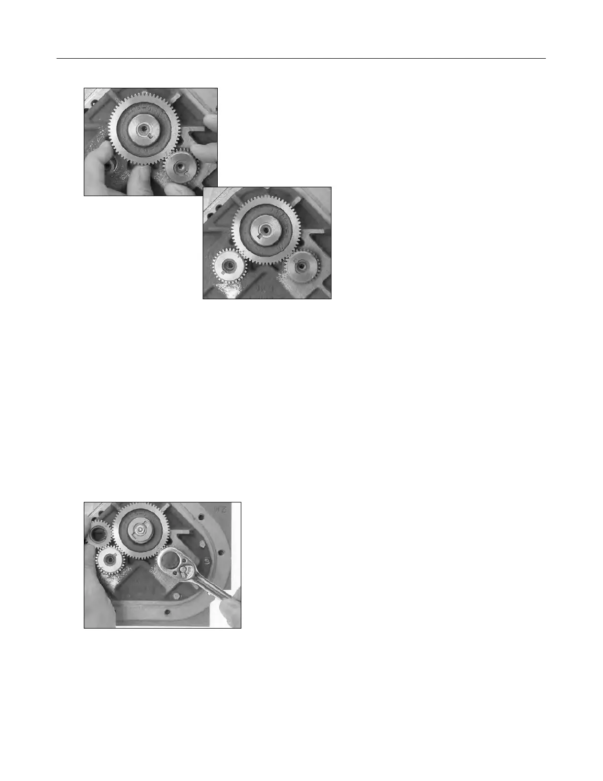
5. Position the spare displacement rotor gear between the right displacement rotor gear
and the blocking rotor gear.
6. Attach the blocking rotor gear with the packing gland driver and screw using the rotor
gear wrench.
7. Rotate the gears to make sure that the rotors turn freely. Burrs, foreign material, or
marred surfaces can restrict the rotor movements. If the rotors do not turn freely, remove
the gears and rotors and deburr and clean the surfaces again.