M & MA Series Meters
36
Get the latest PDF manual:
https://www.lcmeter.com/resources/technical/manuals
Mobile/online version of this manual:
https://www.lcmeter.com/manuals
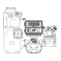
NOTE: MA-4®, M-5®, and MA-5® old style models, M-60® and M-80® current models
have a driven reduction gear attached by a shoulder bolt in the center of the front.
4. Inspect and clean all critical surfaces: gear teeth, rotors, and internal housing faces.
5. Remove any crystalline formations using fine emery cloth or a fine wire brush.
6. Remove nicks and burrs on metal parts with a stone.
7. Remove all grit and other foreign particles.
8. Replace all parts that appear worn or damaged.
Reassembling the Meter
Reassembling the Meter includes the following:
·
Reassembling the bearing plates and rotors
·
Timing the rotor gears
·
Completing meter reassembly
These charts are also available near the end of this topic:
·
Torque Chart
·
Wrench and Socket Size Chart
Reassembling the bearing plates and rotors
Follow this procedure to reassemble the Meter:
1. Replace the non-rotor gear bearing plate to the housing with the bearing plate screws.
NOTE: The rotor gears are on the rear bearing plate of MA-4®, M-5®, and MA-5® old
style models, M-60® and M-80® current models. On all other models, the rotor gears
are on the front bearing