M & MA Series Meters
41
Get the latest PDF manual:
https://www.lcmeter.com/resources/technical/manuals
Mobile/online version of this manual:
https://www.lcmeter.com/manuals
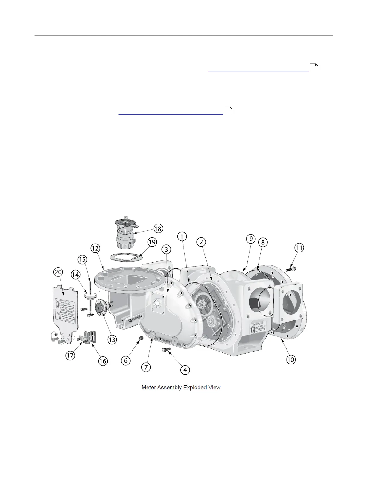
9. Screw the packing gland retaining plate onto the counter bracket using the two retaining
plate screws. See Servicing the Packing Gland in Servicing the Drive Components for
more information.
10.Return the adjuster drive gear (14), the adjuster drive shaft (15), and the drive shaft
bushing (16) to the inside of the counter bracket. Make sure the drive gear is in its
original position. See Reversing the Meter Registration for more information.
11.Screw the retaining spring (17) over the drive shaft bushing and slide the retaining ring
back into the slot on the drive shaft.
12.Screw the standard adjuster (18) onto the adjuster mounting plate (19).
13.Insert the standard adjuster and adjuster mounting plate through the top of the counter
bracket and onto the adjuster drive shaft. Screw the mounting plate onto the counter
bracket.
14.Screw the dust cover onto the counter bracket using the dust cover screws.
23
18