Pulse Output Device
21
Get the latest PDF manual:
https://www.lcmeter.com/resources/technical/manuals
Mobile/online version of this manual:
https://www.lcmeter.com/manuals
Before inserting wires into the terminal block, strip ¼" of insulation off each wire. Turn each
terminal screw counterclockwise a few turns to make sure that the wiring slot is fully open to
accept wire. Insert the stripped end of the wire and tighten the terminal block screw.
Plug the terminal block back into the board if it was removed. Be sure it is properly oriented
with the four pins.
WIRING CONFIGURATIONS
The wiring configuration used depends on the system needs. Check the input requirements of
electronic controls to determine single channel or quadrature output. The POD can be wired
using only one of the two channels (Channel A or B) if the flowmeter has flow in only one
direction. To detect both forward and reverse flow, both channels (which are in quadrature to
each other) must be used. Channel A will lead Channel B by 90º in one flow direction and
Channel B will lead Channel A in the reverse direction. Quadrature is required in most Weights
& Measures approved installations.
CONVERSION TO OPEN DRAIN OUTPUT
As supplied by the factory, the POD has a 2.2 KΩ pull-up resistor to the positive power supply
on each output transistor. The unit can be modified in the field to provide true Open Drain
(Open Collector) outputs if desired.
Follow these steps to modify the POD to Open Drain outputs:
1. Turn off power to the unit and remove the cover by
turning it counterclockwise.
2. Loosen the three circuit board mounting screws
using a Philips screwdriver. Remove the entire
circuit board assembly from the POD housing.
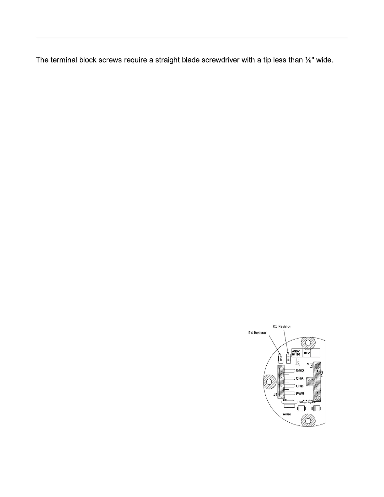
3. With a small tip soldering iron, remove the R4 and
R5 resistors.
4. Carefully, apply heat to one pad of the resistor.
5. When the solder melts, push the resistor off the
circuit board with the tip of the soldering iron.
6. Remove the second resistor using the same method.