Pulse Output Device
22
Get the latest PDF manual:
https://www.lcmeter.com/resources/technical/manuals
Mobile/online version of this manual:
https://www.lcmeter.com/manuals
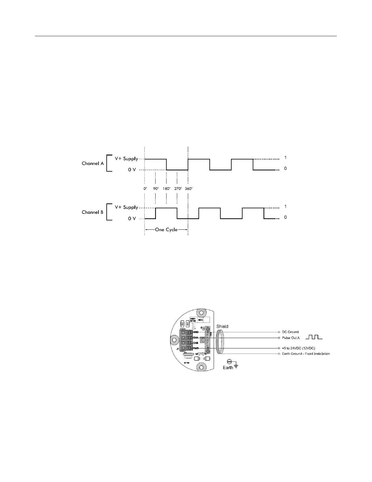
SIGNAL OUTPUT
The diagram below shows the voltage output for a clockwise rotation of the Pulse Output
Device (POD) with Channel A leading Channel B. For reverse flow applications
(counterclockwise) Channel B leads Channel A.
NOTE: Quadrature channel voltage output is 90° out of phase with Channel B.
POD Wiring Schematics
Single Channel Applications – SP4000, SP3850, IT400
Follow these steps when wiring the POD:
1. Use metallic conduit with individual
wires or use 3 conductor, 22
AWG, shielded cable.
2. Strip 1½" off of outer sheathing.
Remove exposed shield and drain
wire and then tape.
3. Strip ¼" insulation from each
conductor and connect to the
terminal blocks.