INSTALLATION
CAUTION: TURN OFF AC POWER TO CIRCUIT BEFORE BEGINNING INSTALLATION.
NEW INSTALLATION - Top mount (For optional restricted ceiling access, see page 5)
1. See Figure 1 before beginning installation.
2. Position metal housing and bar hangers between ceiling or wall joists. Make sure bar hangers are in the correct position
to be mounted. Position metal housing temporarily by hammering nail-in tabs on bar hangers, then secure permanently
with nails or screw. Bar hangers should be level with bottom of joists (Figure 2).
3. Adjust height of metal housing so that the bottom of the housing is just above the ceiling or wall (Figure 3).
4. Reference correct wiring diagram and make proper electrical connections at the J-box in the metal housing (Figures 4 & 5).
CAUTION: The unused lead must be insulated with the remaining provided wire nut or other approved method.
5. Determine directional Chevron requirements. Follow instructions on provided templates to apply the required
Chev-ron(s) (Figure 6).
6. Attach safety chain to holes in trim plate assembly. Snap together the quick-connector harness to connect the LED
board to the transformer.
7. Connect the battery (EL models) after continuous AC power can be provided to the unit.
8. Secure the trim plate assembly using the provided screws.
TESTING: In accordance with NFPA 101 (current life safety code), your emergency lighting system must be tested monthly
for a minimum of 30 seconds and annually for 90 minutes. Refer to your local codes for any additional requirements that may
apply.
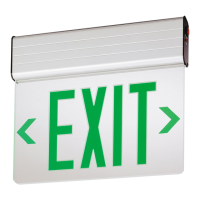
INSTALLATION INSTRUCTIONS for Lithonia Lighting EDGR & EDGRNY Models
OPERATION:
CAUTION: EL Operation: The battery in this unit may not be fully charged. After continuous AC power is connected to the unit,
let battery charge for at least 24 hours, then normal operation of this unit should take effect.
1. Apply AC power to the sign. The LED indicator should turn RED.
2. EL Operation: After the battery has been left to charge for 2 hours, test the sign by pushing the switch. The LED indicator
turns OFF and the sign should remain ON.
3. When the switch is released, EXIT section remains ON and the LED indicator turns back to RED.
PAGE: 2 of 5
Caution: Always turn off AC power to the equipment before servicing. Servicing should be performed only by a qualified service
technician. Use only MANUFACTURER supplied replacement parts.
1. BATTERY: The battery supplied in this equipment requires no maintenance. However, it should be tested periodically (see
TESTING) and replaced when it no longer operates the connected fixtures for the duration of a 30-second or 90-minute test.
The battery supplied in this equipment has a life expectancy of 5-7 years when used in a normal ambient temperature of 72°F.
2. OTHER: Clean exit panel with non-abrasive cloth and non-abrasive cleaner when required.
MAINTENANCE:
SAVE THESE INSTRUCTIONS!
AND DELIVER TO OWNER AFTER INSTALLATION
 Loading...