Document No LM0670 Issue A Rev 2 November 2017 Page 9 of 15
METER MAINTENANCE – GENERAL
This unit should not require regular maintenance providing the installation precautions above are taken
into consideration. The warranty will not be invalidated if the cap is removed to inspect the rotor and its
chamber. Document LM0638 lists all the possible failure scenarios and resolutions and to some extent,
probabilities – see also the FAT Issue section in this manual, p12.
METER MAINTENANCE - TROUBLE SHOOTING
1. If the display or receiving equipment fails to register pulses, first check the display and/or the
receiving equipment by shorting out a pair of input terminals to check for function. (This duplicates the
action of the reed switch). Access is gained to the sensor through the process described below: If the
reed sensor is tested for continuity please ensure a
maximum of 10mA (0.01A) is applied.
1.1.1. Undo the display cover.
1.1.2. The display disc assembly will then be
loose enough to remove, just held by a ribbon
cable. The sensor will still be attached and
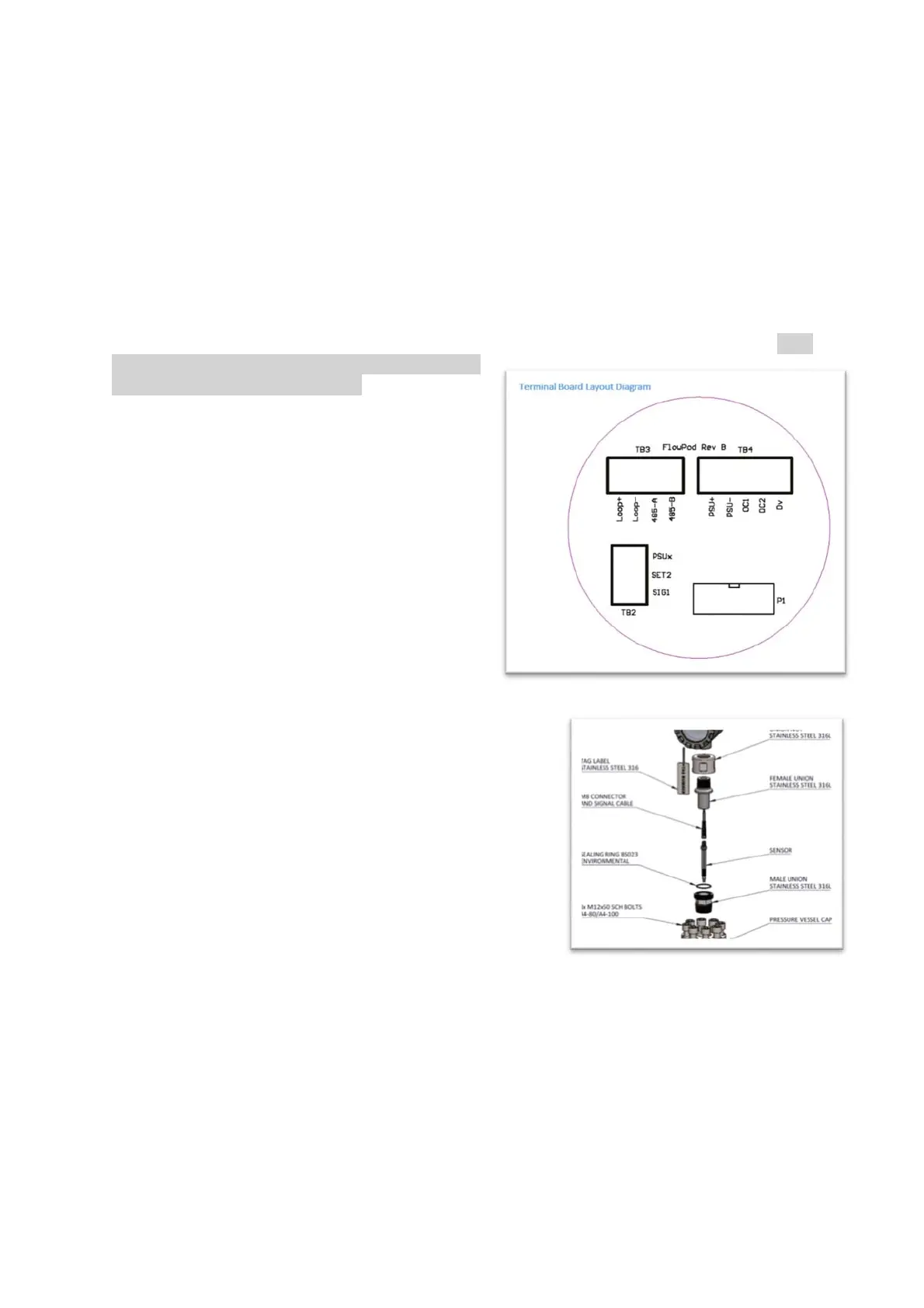
connected to one of the terminal blocks (TB2).
1.1.3. Remove the wires from TB2. Connect
two new wires to TB2 using Sig1 and Set2.
Short these two wires together a number of
times – this duplicates the action of the reed
switch. Help is available at the factory. If the
shorting makes the display count, then it is
likely there is either a problem inside the chamber or with the sensor itself.
1.1.3.1 To replace the sensor undo the nut to
loosen the existing sensor.
1.1.3.2 Gently undo the sensor body to remove
the sensor.
1.1.3.3 Replace with the new sensor ensuring
that a) the sensor is located at the bottom of
its hole and b) the nut locks the sensor in
place
1.1.4. Reassemble ensuring that the sealing O-rings are
kept in place and wiring is re-connected.
1.2 If the instrumentation responds then the next step is to check the wiring between the
reeds and the display (which may also contain a pulse repeater such as a galvanic isolator used
for intrinsically safe systems). (
Integral display– ignore this step
)
1.3 If shorting the field wire connections sequentially produces a result at the display, then
it is likely there is either a problem inside the chamber or with the sensor itself (less likely). (See
para 1.1.3 above for assistance on this)
1.4. The first check avoids breaking down the liquid seal of the flowmeter.
1.4.1 Undo the M8 nut and undo the reed sensor. Moving a magnet in front of this will duplicate
the action of the flowmeter. Replace if necessary. Tighten the nut ensuring the reed