Fig. 4
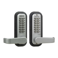
Digital 2835 Lever
*with Passage Function
Installation Instructions
No. Part Name 2835
2
1
3
4
5
Outside Body
Inside Body
Lever Handle
Rubber Trim Plate
Strike Plate
Morsed Striker
Machine Screw M4 x 40mm
Machine Screw M4 x 30mm | 50mm
Wood Screw M4 x 16mm
Extra Code Tumblers (Red)
Extra Non-Code Tumblers (Blue)
Adjustable Latch 2 3/8” - 2 3/4”
Support Pin
Tweezers
Hex Bolts
6
9
10
11
12
13
14
15
16
17
1
1
2
2
1
1
2
1 | 1
4
2
3
1
1
1
2
Spindle
7 1
Allen Wrench
8 1
Step 1: Change User Code/Combinaon (OPTIONAL)
To change user code/combinaon, see instrucons on reverse side.
Step 2: Prep Door for Installaon with Template
Place template (supplied) on door and fold along door’s edge.
Mark holes for 2 3/8” or 2 3/4” backset. Drill holes as instructed.
Note: For pre-prepped 2 1/8“ doors, you only need to drill top hole.
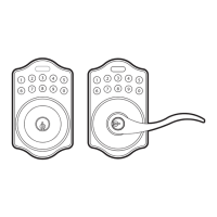
Step 3: Idenfy Door Handing
Right-Hand Doors – From exterior of door, hinges are on right-side (Fig. 1).
Le-Hand Doors – From exterior of door, hinges are on le-side (Fig. 2).
For Right-Hand Doors: Install Support Pin (#15) in posion ‘A’.
For Le-Hand Doors: Install the Support Pin (#15) in posion ‘B’.
Now, install/screw Hex Bolts (#17) into the top and boom as shown.
Step 4: Install Lever Handles
Using Allen Wrench (#8), install levers to the inside and outside bodies.
Secure with set screws.
Note: Levers should point towards the door hinges.
Note: The 2835 is equipped with a built-in slip clutch lever handle to prevent
damage in the event of an aempted forced entry.
If lever handle is in posion shown (far right), pull lever back to desired posion.
Step 5: Adjust Latch (if necessary) and Install
Adjustable Latch (#14) is preset to 2 3/8” backset.
To adjust: Remove plasc plug, slide to 2 3/4”, and replace plasc plug as shown (Fig. 5).
Insert Adjustable Latch (#14) into the door.
Secure with two (2) Wood Screws (#11).
Fig. 3
Fig. 5
Connued on Reverse Side
RIGHT HAND LEFT HAND
Support Pin
15
1. Remove Plastic Plug
2. Move/Slide to 2 3/4”
3. Replace Plastic Plug
IMPORTANT INFORMATION ABOUT YOUR DIGITAL 2835
1. When the door is closed, the system locks automacally.
2. From the inside, unlock using the Lever Handle.
3. From the outside, unlock by pressing ‘C’ (CLEAR), followed
by your User Code.
4. The 2835 is equipped with a PASSAGE FUNCTION,
allowing you to leave the door unlocked.
-To enable the passage funcon:
Press ‘C’ (CLEAR), then ‘Y’ (PASSAGE), then enter User Code.
-To disable the passage funcon:
Press ‘Y’ (PASSAGE), followed by ‘C’ (CLEAR).
-To disable the passage funcon PERMANENTLY:
Remove the ‘Y’ (PASSAGE) tumbler, leaving that slot empty.
IMPORTANT: Always press and hold the ‘C’ Buon when
removing and inserng Tumblers. Refer to ‘How to Change
Code’ instrucons on reverse side.
* *
Slip Clutch