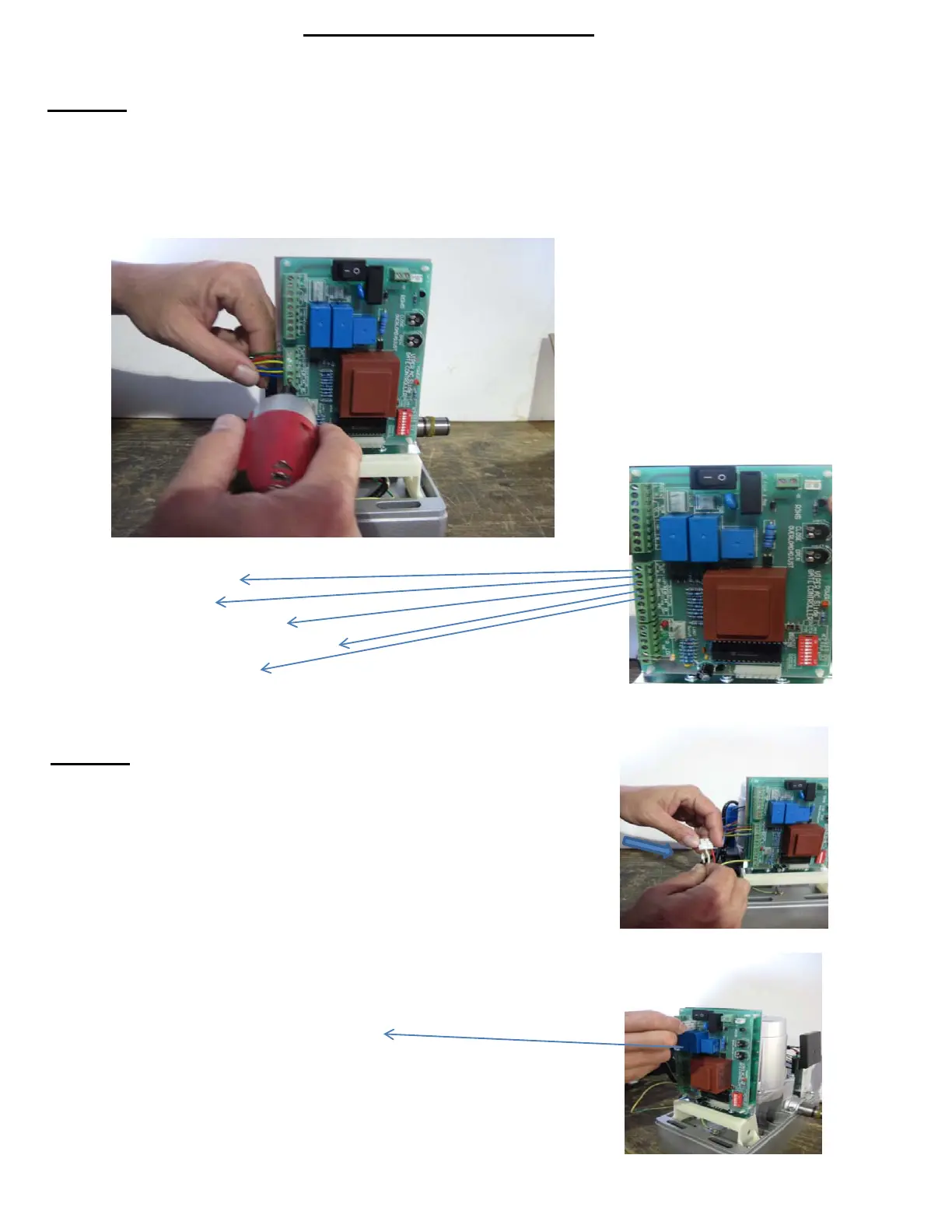
Step #4
Now you will begin the installation by screwing the wires that are coming
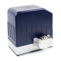
from the small Receiver Board onto the Terminals (see Pic 1, right) from
the Control Board, in the following order:
Terminal 10 - GREEN WIRE
Terminal 11 - RED WIRE
Terminal 12 - YELLOW WIRE (any)
Terminal 13 - YELLOW & BLUE WIRE (any )
Terminal 14 - BLUE WIRE (any)
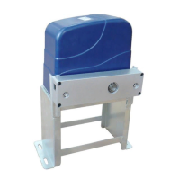
Step #5
Next, take the set of wires coming from the motor and connect the
red and black wires anywhere onto the plug.
(as shown on the pic, right)
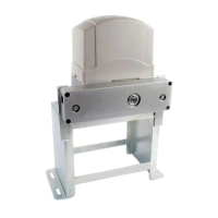
Once you have connected those wires, you will then take that plug
and connect it to the Control Board on the section labeled:
"MOTOR"
(as shown on the pic, right)
Pic 1
8