DKL400UY SLIDING GATE OPERATOR
7
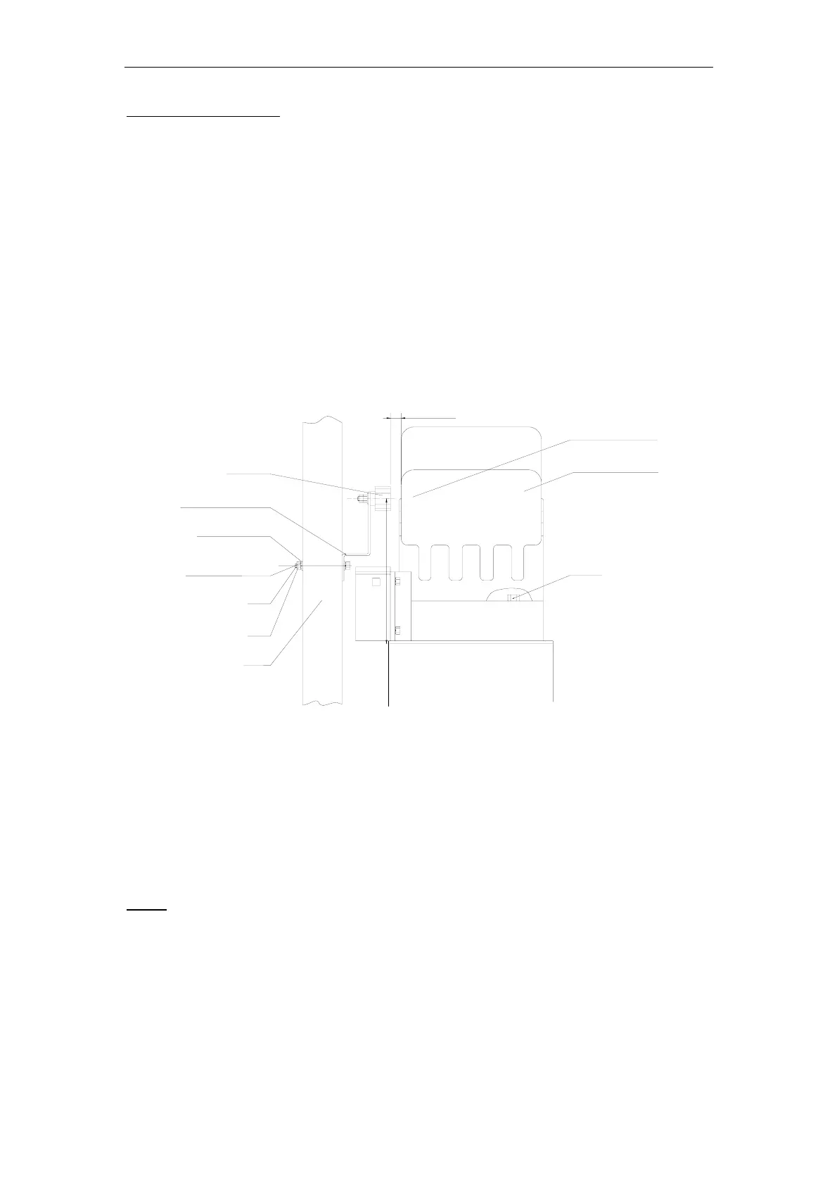
Magnets for Limit Switch
Install the magnet and magnetic limit switch as shown in Fig.7. The magnet and limit switch
are used to control the position of the gate. When the magnet is installed, release the gear
clutch and push the sliding gate manually to pre-determine the position. Fit the magnet
bracket to the gate and then tighten the gear clutch. The lower bracket is for open position
and higher bracket is for close position. Finally adjust the magnet to the proper position by
moving the gate with the motor. The magnet should be .39 - .59 “away from the magnetic
limit switch. If it is too far away, the switch will fail to work. The distance between the magnet
and the operator should be @ ½” (12mm) with the operator cover on. Adjust the position of
the magnetic limit switch until the positions of the opening and closing meet the requirement.
Important Note: Please note the two magnet brackets (fixed plate) are different: one is
higher and another is lower. Verify and if necessary exchange the two brackets
position. Also if necessary exchange the limit switch wires CL (close) and OP (open).
Another common problem is there are four reed switches inside the magnetic limit
switch: two are upper and two are lower. The magnet position can be installed in the
middle so it inducts both reed switches. Solution: adjust the magnet upper or lower.
214.5mm
10-15mm
Gate
Nut
Bolt
Spring washer
Plain washer
Magnet bracket
Magnet
Nut
Magnetic limit
switch inside
Gate operator
Fig.7
7. Electrical
The control box should be equipped with a single-phase breaker (10A). Make sure that the
power is OFF before making any electrical connections. Remove the cover of the control box,
perform the wiring and replace the cover again. (See control board scheme and wiring notes
for control board)
Power
Using 18-3 gauge electrical wire, wire a standard grounded plug to your control board using
standard electricians wiring practices. Wire the opposite end of this cable to the E, N, L
contacts (block 20) of the control board. Connect L to the power or brown line (or red line), N
to the neutral or blue line (or black line), and E to the ground line (yellow/green)