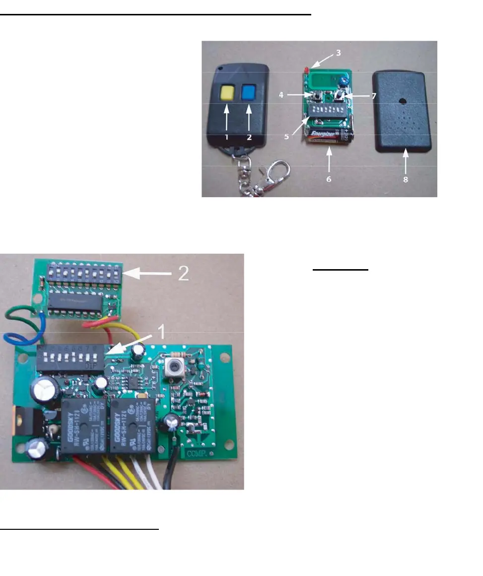
Transmitter/Remote Control (shown in Figure 9)
1. Yellow Button Channel
2. Blue Button Channel
3. Indicator Light
4. Yellow Button Channel – exposed
5. DIP Switch
6. Battery
7. Blue Button Channel – exposed
8. Back side cover
Figu
re 9
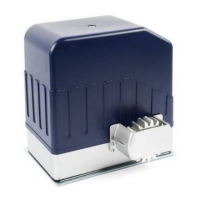
Receiver
1. Channel 1 DIP Switch (yellow
button
on remote control
transmitter)
2. Channel 2 Dip Switch
(Secondary, Multi-Code
co
mpatible, blue button on
remote control transmitter)
The
red and black wires are 24 volt
po
wer input. The two yellow are the
ch
annel 1, the two white are
ch
annel 2, and the black wire is the
antenna wire
Figure 10
Figure 10
Setting the Transmitter DIP Switches:
There
are a total of eight (8) transmitter DIP switches. Each one can be placed in three (3) different positions
(+,
0, -). DO NOT set all of the switches to the same position, for example: all +, all 0 or all -. Once the
DI
P switches have been set to a personal code, replace and close the cover.
11