6
Follow the Programming section of this
manual on pages 12-15.
Step 6Step 5
NOTE: If during operation of the lock, the lock
emits 10 rapid beeps and 10 ashes of the LED
light, it is an indicator that the bolt/latch of the lock
is binding with the door strike plate and/or frame. If
this occurs, the door and/or strike plate may need
to be aligned or adjusted. It may also be an indica-
tor that the locking nuts are over tightened on the
screw posts.
Test the operation several times (as indicated
below) while the door is open. Close the door and
test the unit again. Make sure there is no binding
between the bolt/latch and the door strike plate and/
or frame. Adjust alignment if necessary.
To lock and unlock press: = then `
NOTE: Do not touch the rear unit connector pins
(male connector) against any metal or other conductive
surfaces. This may short the batteries and cause
damage to the lock.
NOTE: An audible triple beep and three ashes of
the LED light indicate that the lock was connected
properly. If you do not hear these beeps, separate the
units, press the “C” button on the keypad and reconnect
the front and rear units on the door.
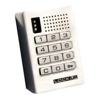
Slide the front unit (A) and rear unit (B) together
making sure that the pins of the rear unit align with the
front unit (A) connector.
Step 3
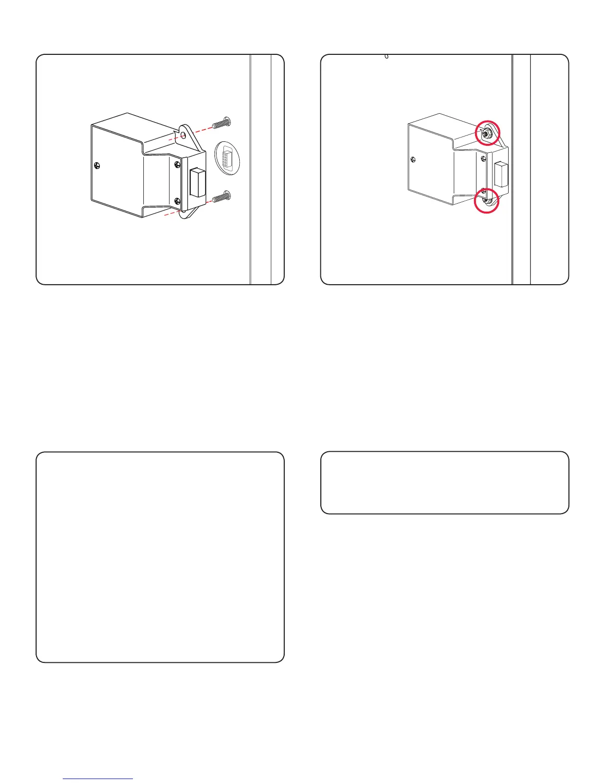
Place the locking nuts (C) over the mounting screws
and tighten to secure the lock to the door.
Step 4