Surface mount speaker D-100-F diagram
Wiring Hole
Replace Wiring cover
Initial
Mounting
Screw
Second
Mounting
Screw
Wall /
Mounting
Surface
Wall /
Mounting
Surface
Wall /
Mounting
Surface
Fig 2
Fig 3
Fig 4
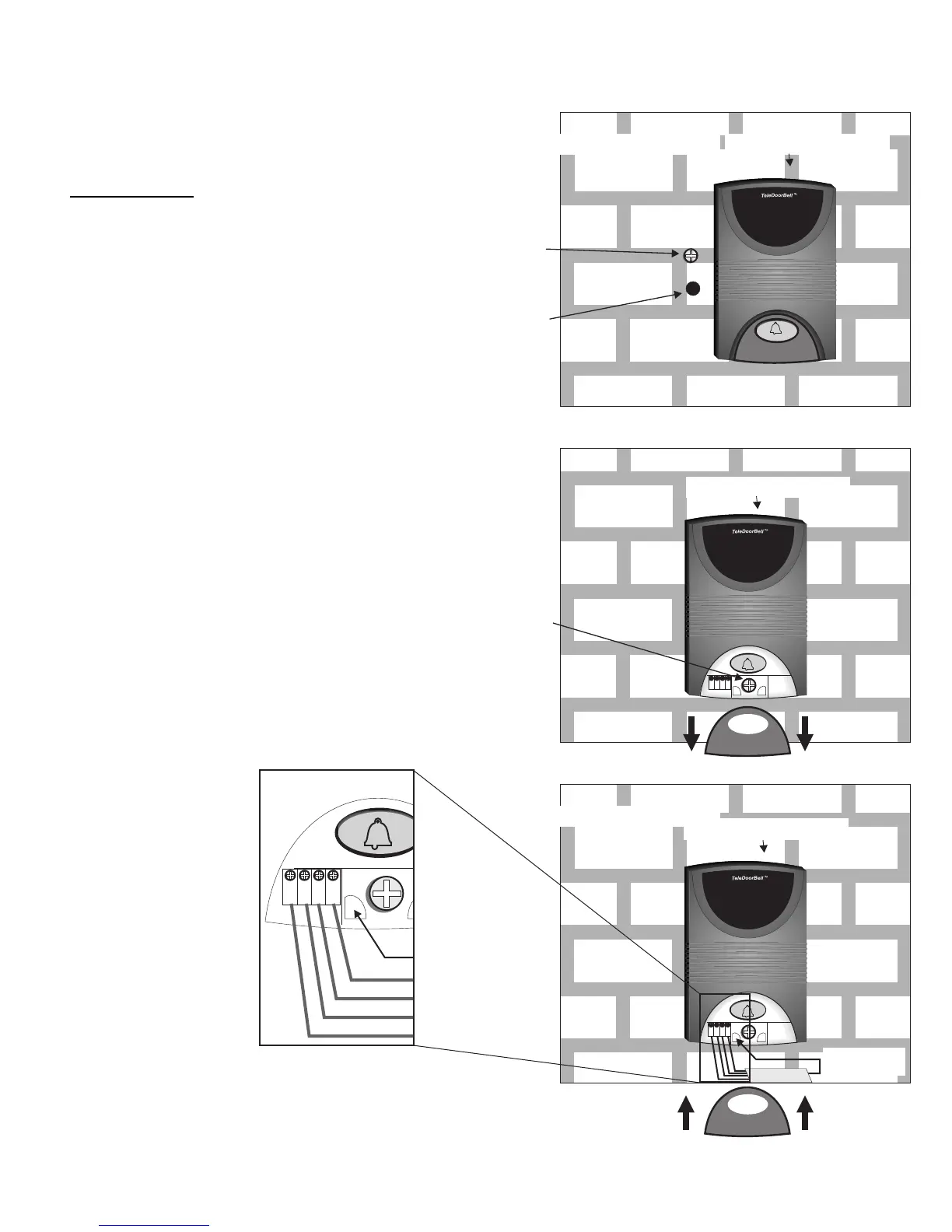
Installation
1) First drive an initial mounting screw 2” above
the door speaker wiring hole leaving about 1/4”
of screw shaft extending from wall.
2) Thread wire through opening at bottom of unit
Note: We recommend that you use
silicon sealer to protect the wiring
around the hole
3) Hang The D-100-F speaker on initial
mounting screw
4) Secure the D-100-F speaker to the wall with
secondary mounting screw. See Fig 3
5) Connect the four wires to the wiring post of
the D-100-F speaker. See fig 4
6) Replace the wiring cover back on the speaker
Page 5
D-100-F Door Speaker
D-100-F Door Speaker
D-100-F Door Speaker
Wire runs through
opening and into hole
Green
Yellow
Red
Black
 Loading...