EasyManuals Logo

Logenex TeleDoorBell User Manual

Logenex TeleDoorBell
10 pages
To Next Page IconTo Next Page
To Previous Page IconTo Previous Page
Page #6 background imageLoading...
Page #6 background image
Installation Guide
TeleDoorBell
TM
Page 6
Installation Guide
TeleDoorBell
TM
Page 6
Ring On/Off Relay Contacts Door Spkr 2 Door Spkr 1 Tele Line In & Out
Power Plug
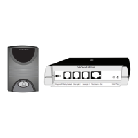
TeleDoorBell Unit
V-200
Existing
doorbell
Transformer
120V AC
Already connected
OUT
OUT
IN
IN
Existing
doorbell switch
(to be removed)
TransformerFront Door
Door Bell
Disconnect
switch and connect
wires together
Wire is reconnected
to the TeleDoorBell
Doorbell rewiring section
RJ45 Modular Wire
(Supplied with Unit)
RJ11 Modular Wire
(Supplied with unit)
Use a 22 gauge 4
conductor wire (Max
Length 250 ft) to
connect from
controller to speaker
OUT
OUT
IN
IN
RJ31X
(CA38A)
Alarm Jack
TELCO IN LINE
from phone company
Alarm jack
connection
only if alarm
monitored
PRESS
This contact
is activated
by pressing
door speaker
button
To Door Strike
or any activation device
PRESS
Red
Yellow
Grey
Blue
Black
Green
(3rd Relay)
To Door Strike
or any activation device
RJ31X
(CA38A)
Data Jack
16V AC
Output
To
Phone
Audio Video
- Remove access cover
- wire your speaker to the
appropriate colour code of
the audio terminal side
Speaker Connection
09-01

Questions and Answers:

Question and Answer IconNeed help?

Do you have a question about the Logenex TeleDoorBell and is the answer not in the manual?

Logenex TeleDoorBell Specifications

General IconGeneral
BrandLogenex
ModelTeleDoorBell
CategoryIntercom System
LanguageEnglish

Related product manuals