5
analog audio into the pedal and one producing analog audio out, as well as a
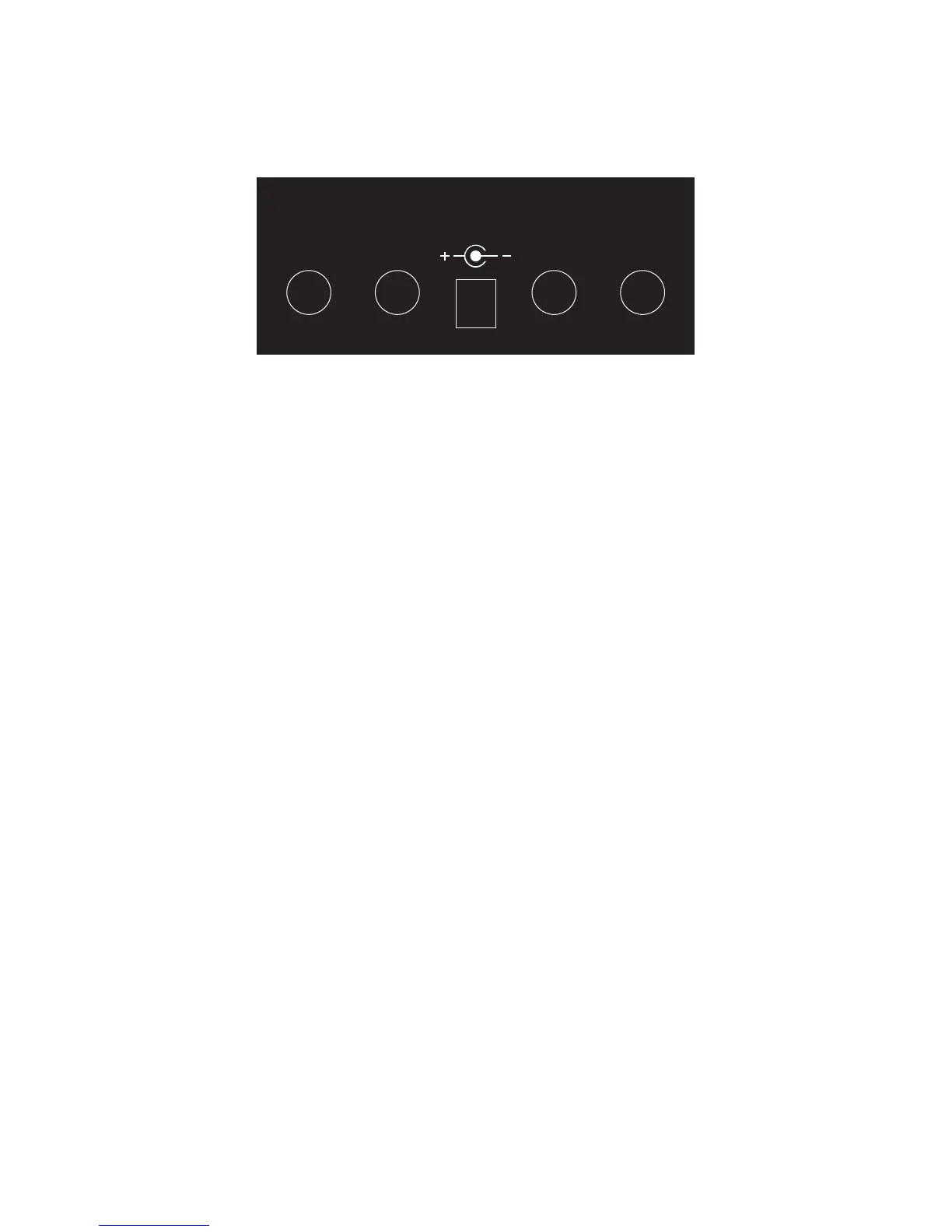
power jack. The connectors are laid out as shown here:
L(M) OUT R L(M) IN R
9V DC
2.1. Power Jack
Connect the included 9 Volt power supply to an AC outlet and to the power jack
at the back of the unit. The EPSi uses the most common voltage polarity for
effects pedals with the positive potential on the outside sleeve of the connector.
Caution: When using a different power supply, make sure it conforms to the
specifications given at the end of this document. Insufficient or excessive
current/voltage can easily result in damaging the electronic circuits inside the
pedal and render it inoperable.
As soon as the EPSi is powered, it will start right away and go through its startup
sequence. See the user interface section for more on this.
2.2. Audio Inputs
Facing the back of the unit, the input connectors are on the right. The EPSi can
take in either a mono or a stereo signal. If a single jack is plugged in the L(M)
input – which stands for “Left(Mono)” – the signal coming from that input will be
copied onto the right side channel creating an internal split. If a single jack is
plugged in the R input – which stands for “Right” – no direct signal will go to the
left side channel. The impedance of the input stage is set so that an electric
guitar can be plugged in directly without suffering much loss in brightness in the
sound.
EPSi features an analog direct path so as not to add any latency to the dry
signal. This dry path can be disabled through the user interface.
2.3. Audio Outputs