6
Facing the back of the unit, the output connectors are on the left. Plugging a
single jack into the L(M) connector – which stands for “Left(Mono)” – has no
effect on the dry path, but causes the left and the right channels of the processed
audio to be summed.
2.4. SD Card Slot
The EPSi uses impulse responses stored on an SD Card. The unit arrived to you
with an SD Card pre-loaded with a collection of impulse responses. If, on power-
up the EPSi does not detect the presence of a card, a test impulse response
generated internally is used instead. Cards can be inserted and removed while
the unit is running. Each time a card is inserted, the system will inspect its
contents and adapt accordingly without interrupting the audio processing. SDHC
Cards are currently not supported.
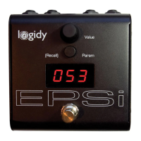
3. EPSi User Interface
The EPSi features a simple user interface including an endless value rotary
control, a button for stepping through parameters, a foot switch and a 3 digit LED
character display.
Note: Because the front panel of the EPSi does not explicitly name parameters,
it is possible for us to add/remove/change parameters in software. Make sure
that the version of this document matches the version of the firmware that is
running on your EPSi.
3.1. Firmware Version
On power up the EPSi first displays the version number of the firmware being
currently run. If an SD Card is present the system will quickly proceed with the
file initialization and take over the display. If a card is not present, the firmware
version number will show until the user interface is interacted with.
The Firmware on the EPSi can be replaced via the SDCard. Exact details on how
to perform a firmware update are provided on our website along with the new
program file.
3.2. Changing Parameter Values
Parameters on the EPSi are changed one at a time by stepping through them
with the “Param” button and using the “Value” knob.