11
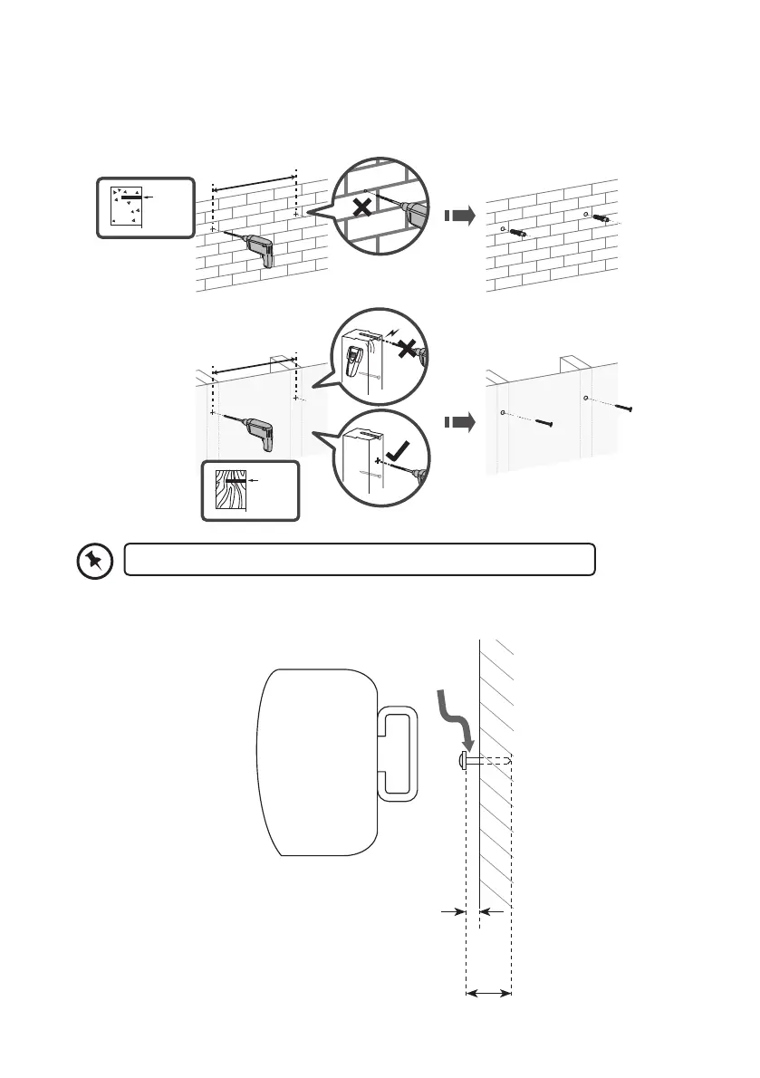
3. Drill 2 parallel holes (Ø ~6 mm each according to wall type) in the wall. Fix two screws
onto the wall. They should be parallel to each other. The distance between the two
screws should be 657 mm.
ø2.5~3mm
ø ~6mm
657 mm
657 mm
5 mm
25-30 mm
4. Leave a 5 mm gap between the wall and the screw’s head. Lift the unit with the attached
wall brackets over the heads of the screws and slot into place.
Wall mounting with dowels and screws
Wall mounting with screws only
Make sure that the mounting screws are in the centre of the timer stud.
L32SBIN16_IB_Final191216V8.indd 11 17/12/2019 11:08