LogTag TRIX-8 V2 Work Instruction Manual Revision 10.17 Page 44/44
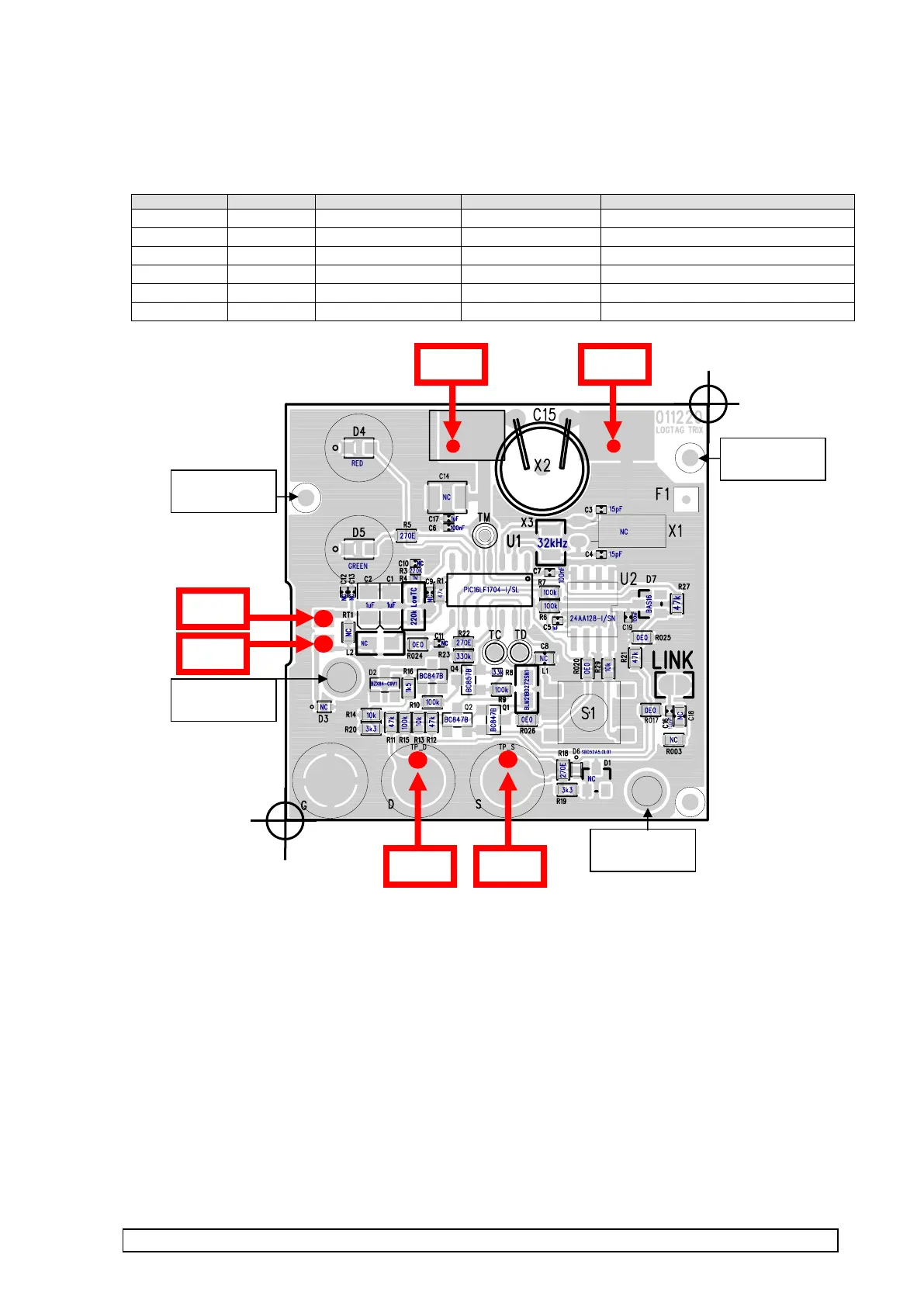
APPENDIX 6 : PCBA Test point locations – 011220 PCBA
PCBA Test & Cal connects to the PCBA via the following connection points.
Note :
These locations are designed to be the same as all past TRIX-8 PCBAs to allow existing fixtures to operate
(This is why the +V & GND positions are different to the ICP locations).
HOWEVER – some in some TRIX fixtures the RT1 & RT2 positions may be offset in the X direction which
will cause no connectivity on this PCBA. This is because the 080719 PCBA has small solder pads for the
thermistor soldering. Special attention is required to ensure the fixture RT1,RT2 test point positions are
compatible.