LogTag UTRIX Work Instruction Manual Revision 1.07 MP Release Page 20/52
1.10 Solder USB connector, Electro-cap & Bridge J1
Equipment Required:
• Temperature controlled soldering iron
Procedure
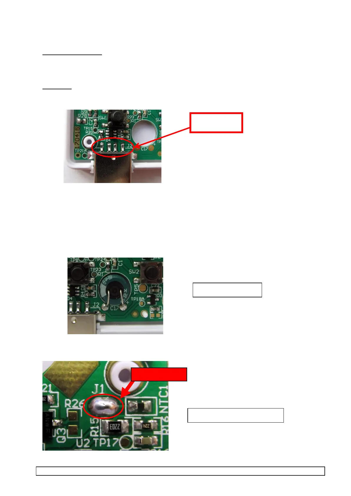
1. Solder the 4 pins of the USB connector to the PCB taking care not to apply too much solder
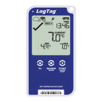
2. Pre-bend and pre-trim leads of electrolytic cap (470uF,4V).
- The Cap must sit flush against the bottom of the rear plastic case once soldered
- Legs must be pre-trimmed to correct length, so they are flush with rear of the PCBA and sit flush
against the Cap body
- Correct polarity must be observed.
3. Position Electro cap in the PCB cut-out as shown, insert legs in through-holes and top-solder to
PCBA.
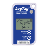
4. Locate J1 and solder bridge the two pads.