Home
Lombardini
Engine
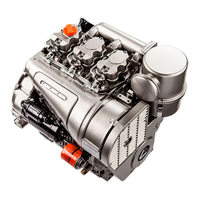
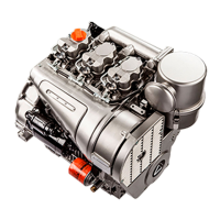
11 LD 535-3
Lombardini 11 LD 535-3 User Manual
5
of 1
of 1 rating
68 pages
Give review
Manual
Specs
To Next Page
To Next Page
Loading...
1
1
1 LD 535-3
1
1 LD 625-3
1
1 LD 626-3
WORKSHOP
MANUAL
1
1 LD series engines, code 1-5302-296
3st Edition
COMPILER TECO/ATL
REG. CODE
1-5302-296
MODEL N°
50510
DATE OF ISSUE
01.89
REVISION
02
ENDORSED
DATE
17.04.2003
2
Table of Contents
Default Chapter
1
Hydraulic Pump 4Th P.t.o., Group
1
Hydraulic Pump 3Rd P.t.o., Group
2
Table of Contents
4
Itroubleshooting
9
Safety Decals - Safety Instructions
10
Model Number and Identification
12
4 Technical Data
13
5 Vcharacteristic Curves
14
6 Overall Dimensions
15
7 Maintenance- Recommended Oil Type - Refilling
16
8 Disassembly/Reassembly
19
Aír Cleaner
19
Air Cleaner Components
19
Exhaust Manifold
19
Belt Tension Adjustment
20
Fan Control Belt
20
Intake Manifold
20
Shroud and Plates
20
Blower Assembly
21
Blower Assembly Components with 14 a Alternator
21
Blower Assembly Components with 21 a Alternator
21
Blower Control Pulley Diameter
22
Crankshaft Pulley
22
Gear Cover, Timing Side
22
Tank
22
Compression Release (Optional)
23
Flywheel
23
Valve / Rocker Arm Clearance
23
Cylinder Head
24
Injector
24
Injector Projectiion
24
Rocker Arm Assembly
24
Valve Material
25
Valve Springs
25
Vatves
25
Dimensions and Clearance between Guides and Valves (MM)
26
Valve Guide Insertion
26
Valve Guides and Cylinder Head Housìngs
26
Pushrod Tube Spring Fitting
27
Valve Seat Lapping
27
Valve Seats and Housings
27
Checking that Piston Is an Original Part
28
Checks and Cyiinder Roughness
28
Cylinder
28
Piston
28
Piston Rings - End Gaps (MM)
29
Piston Rings - Fitting Sequence
29
Piston Weight
29
Pistons Rings - Clearance between Grooves (MM)
29
Connecting Rod
30
Connecting Rod Small End Bearing and Pin
30
Piston - Refitting
30
Piston Clearance
30
Connecting Rod Alignment
31
Connecting Rod Big End Bearing
31
Connecting Rod Weight
31
Camshaft Gear
32
Main Bearing Support, Gear Side
32
Oil Pump Gear
32
Timing Gear
32
Crankshaft
33
Crankshaft Center Main Bearing Supports
33
Crankshaft Removal
33
Main Bearing Support, Flywheel Side
33
Checking Main Journals and Crank Pins
34
Crankshaft Journal Radius
34
Crankshaft Lubrication Ducts
34
Main Journal and Crank Pin Diameter (MM)
34
Clearance between Main Journals/Crank Pins and Connecting Rod Bearings (MM)
35
Main Bearing and Connecting Rod Big End Bearing Inside Diameter
35
Use an Inside Micrometer to Measure the Inside Diameter of Main Bearings
35
Crankshaft End Play
36
Main Bearing Housings
36
Main Bearing Supports
36
Camshaft
37
Dimensions of Camshaft Journals and Housings (MM)
37
How to Measure Camshaft Bearing and Journal Inside Diameter
37
Use an Outside Micrometer Gauge to Measure Camshaft Lobe Height
37
Camshaft End Play
38
Camshaft Timing
38
Intake/Exhaust Cam Height
38
Valve Timing Without Considering Timing Marks
38
Valve Timing Check
39
Hydraulic Pump P.t.o
40
Use of 3Rd and 4Th P.t.o
40
Mechanical Speed Governor
41
Mechanical Speed Governor Components (Standard)
41
Mechanical Speed Governor Operation (Standard)
41
Mechanical Speed Governor Components for Special Generating Sets
42
Mechanical Speed Governor Setting
42
Spring for Extra Fuel Supply at Starting
42
Electronic Speed Governor
43
ELECTRONIC SPEED GOVERNOR (Optional)
43
Electronic Speed Governor Layout
43
Electronic Speed Governor Control Box
44
Engine Running with Electronic Speed Governor
44
Starting with Electronic Speed Governor
44
9 Lubrication System
45
Oil Filter Cartridge
46
Oil Pressure Check
46
Oil Pressure Relief Valve
46
Oil Pump
46
Oil Pressure Curve at Full Speed
47
Oil Pressure Curve at Idling Speed
47
10 Xfuel System
48
Fuel Feeding Pump
48
Fuel Feeding Pump Drive Rod Protrusion
48
Fuel Feeding/Injection Circuit
48
Fuel Fliter
48
Injection Pump
49
Injection Pump Type Bosch
49
Injection Pump Type LOMBARDINI - OMAP
49
How to Check Injection Pump Delivery Valve Sealing
50
How to Check Plunger and Barrel for Internal Leakage
50
Plunger
50
Bosch Injection Pump Replacement - Reference Mark on Delivery Side
51
Test Data for Injection Pump Delivery at the Test Bed - Pump Type Bosch
51
Test Data for Injection Pump Delivery at the Test Bed - Pump Type LOMBARDINI-OMAP
51
Bosch Injection Pump Replacement - Shim Reference Number
52
LOMBARDINI-OMAP Injection Pump Replacement
52
(Static) Injection Timing
53
Injection Timing Check
53
Injection Timing Checking Device
53
Injection Timing Correction
54
Injection Timing Reference Marks on Crankcase and Flywheel
54
Injection Timing Reference Marks on the Pulley and the Gear Cover
54
Injector
55
Injector Setting
55
Nozzle
55
11 Electric System
56
V, 14 a Alternator
56
Electric Starting Layout Without Battery Charging Light
56
Electrical Starting Layout with Battery Charging Iight
56
12 V, 21 a Alternator
57
Alternator Battery Charger Curve (12 V, 21 A)
57
Alternator Battery Charger Curve (12.5 V, 14A)
57
Checking for Cable Continuity
58
Magnetization Checking Tool (Part No. 7000-9727-001)
58
Voltage Regulator
58
Connections for LOMBARDINI-DUCATI Voltage Regulator
59
How to Check Voltage Regulator for Proper Operation
59
33 A Bosch G1 Alternator Battery Charger Curve
60
Alternator Type Bosch Gil 14 V, 33 a Layout
60
Alternator Type Bosch Gl 14 V, 33 a
60
Characteristic Curves for Starting Motor Type Bosch JF (R) 12 V
61
Starting Motor
61
Starting Motor Layout
61
12 Settings
62
Full Speed Setting in No-Load Conditions (Standard)
62
Injection Pump Delivery Setting
62
Ldling Speed Setting in No-Load Conditions (Standard)
62
Injection Pump Delivery Setting with Engine at the Torque Dynamometer
63
Required Settings (as most Commonly Applies)
63
Stop Setting
63
Storage
64
Temporary Protection (1÷6 Months)
64
Permanent Protection (over 6 Months)
64
How to Prepare the Engine for Operation
64
14 Main Torque Specifications and Use of Sealants
66
Use of Sealants
66
5
Based on 1 rating
Ask a question
Give review
Questions and Answers:
Need help?
Do you have a question about the Lombardini 11 LD 535-3 and is the answer not in the manual?
Ask a question
Lombardini 11 LD 535-3 Specifications
General
Engine Type
Diesel
Number of Cylinders
3
Fuel System
Indirect injection
Fuel Type
Diesel
Cooling System
Air
Starting System
Electric start
Related product manuals
Lombardini 11 LD 625-3
106 pages
Lombardini 11 LD 626-3
106 pages
Lombardini 11 LD Series
68 pages
Lombardini 15 LD 225
74 pages
Lombardini 15 LD 315
74 pages
Lombardini 15 LD 400
74 pages
Lombardini 15 LD 440
160 pages
Lombardini 15 LD 350
160 pages
Lombardini 15 LD 500
44 pages
Lombardini 12 LD 477/2
48 pages
Lombardini 4 LD 705
12 pages
Lombardini 9 LD 625-2
88 pages